These are some instructions for installing the Plano #10821 walkways on the Walthers Thrall 4750cf covered hopper.
These parts were developed and applied to an undecorated model. They can be added to a decorated model. mainly paint touch up would be the
main difference of what be needed.
| Clickable photos |
Description of what is shown in the photo |
|
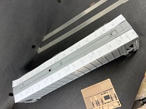
There are eight holes in the roof that are used for mounting the plastic roofwalk supplied with the model. These will need to be filled, possibly using the pins
of the plastic roofwalk - install and trim flush with roof. Cut out the drill templates at the boarder lines. Suggest using small pieces of double stick tape
to tape the templates to the roof of the car. the arrows point to the center of the car and that edge of the template should rest against the raised part of the roof.
|
|
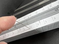
Using the supplied T pin, press a drill pilot point in the center
of each '+' symbol on the template. Once all pilot points are pressed, remove templates and drill a #78 hole in each pilot point.
|
|
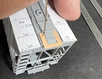
The U shaped piece on the parts fret is a drill template that will be used to drill holes in the end of the roof for installing the center end supports.
Position this template so it straddles the raised portion and rest against the rib as shown in the photo. At each dimple in the edge of the template, mark and drill a
#78 hole.
|
|
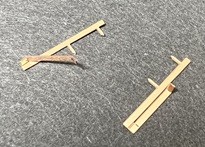
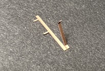
OK, will admit, these little brackets are a challenge to form. Why do you think there are two sets supplied. Have found that it is easier to first bend the outer
most section up about 45 degrees. the half etch bend line will always be the inside of the bend. The upper left part is fully formed. Lower right is the first section bent.
|
|
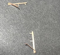
Now the longer section is bent up another 45 degrees. This will be the final shape of these three parts of the bracket. They will represent the angled
brackets the support the end crossover portion of the roofwalk.
|
|
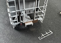
Now you can bend the three sections over 90 degrees so it is perpendicular to the center support bars. The mounting pins of these formed parts insert into the holes drilled
using the U shaped template. The floating end of the angled brackets should rest against the end of the car and be glued to the end of the car.
|
|
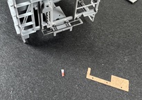
Adding the couple crossover platforms will also require some holes to be plugged. Again suggesting adding the plastic platforms and then trimming flush with the end frame
of the car end. There are two different templates supplied for drilling new holes for adding the new mounting brackets. The one with 3 holes if for the B end. Position a
template so it straddles the coupler box. Drill a #78 hole in each hole of the template.
|
|
Add yes there are two different platform brackets. The A end bracket with 4 mounting pins will insert and be CA'd to the holes drilled in the A end. The B end bracket
has been modified to work around the brake linkage. Also note there is a piece the frame that needs to be removed, highlighted with red in the photo above. Here is the
new B end platform bracket installed. CA in place.
|


