| How to photos |
How to discription |
How to photos |
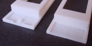 |
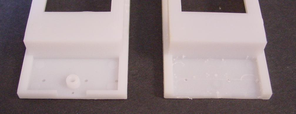
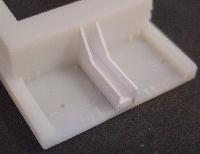
The articulated ends need to be modified before adding prototypical articulation joints. The screw boss for the original
metal weight needs to be remove flush with the bottom surface. The end faces will also need to be removed as shown.
|
 |
 |
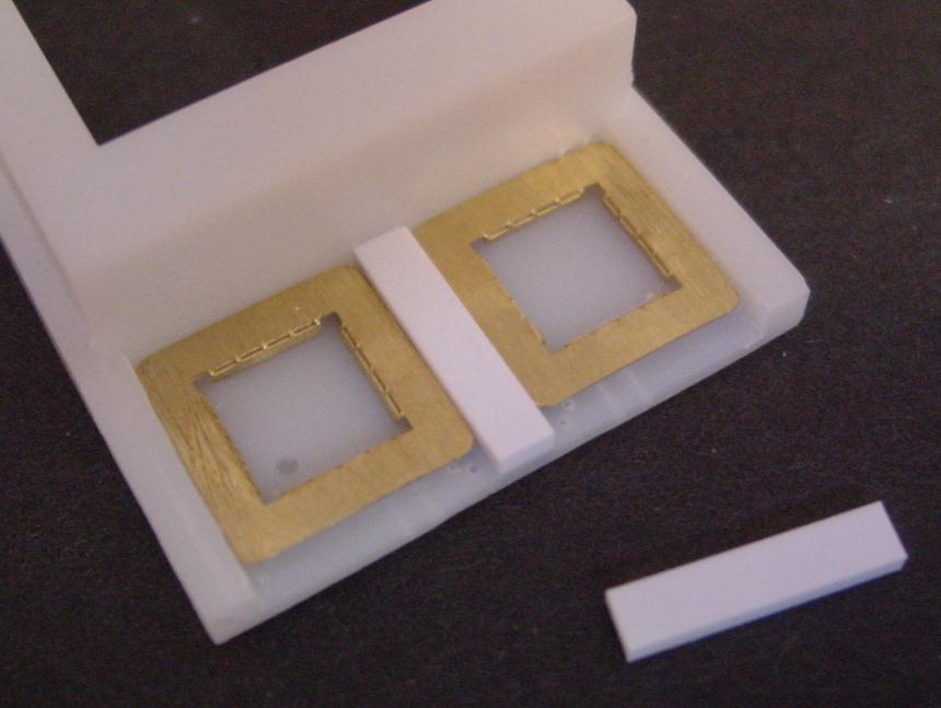
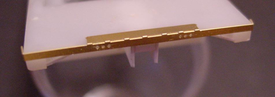
Using the two supplied brass fixtures, a piece of .120 X .060 X .580 styrene is center on the end. This will hold the new
articulation joints at the proper height in the center.
|
 |
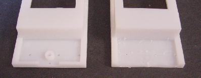
New boxes (bolster?) are built to enclose the articulation joints. The brass template helps to make
sure they are all the same size. New sides are made from styrene.
|
 |
 |
Here you can see box sides attached ready for the new articulation joints. |
 |
 |
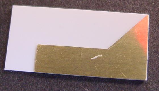
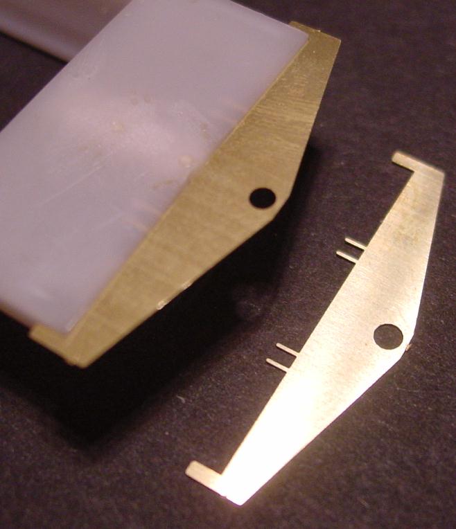
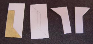
These two photos show a couple of the fixtures I am using to make sure everything lines up. The one on the left is a drill template.
The holes drilled with this template serve two purposes. First they are used to hold the alignment fixture seen to the right. The fixture helps align the articulation
joints on each of the wells. Later the drilled holes will be used to hold some stabilizer arms. |
 |
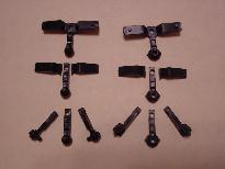 |
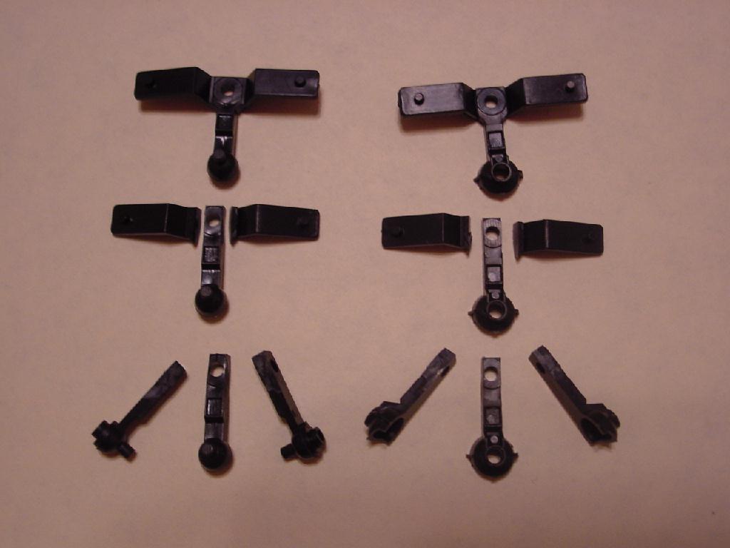
Here you can see how I modified the joints to fit my needs. The top parts are as used by Athearn. The middle parts are with
their wings clipped. And the bottom parts are several parts clipped, cleaned up and ready to use. |
 |
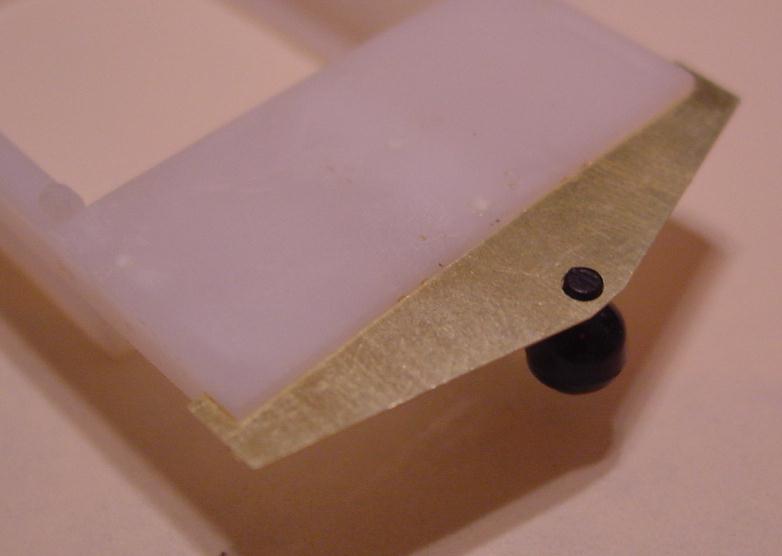
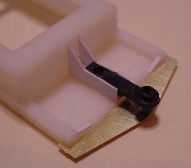
Here you can see how the fixture helps align the male articulated joint in place while it is glued in place. Is the fixture really needed?
Probably not but at least you know they are all spaced the distance out. |
 |
 |
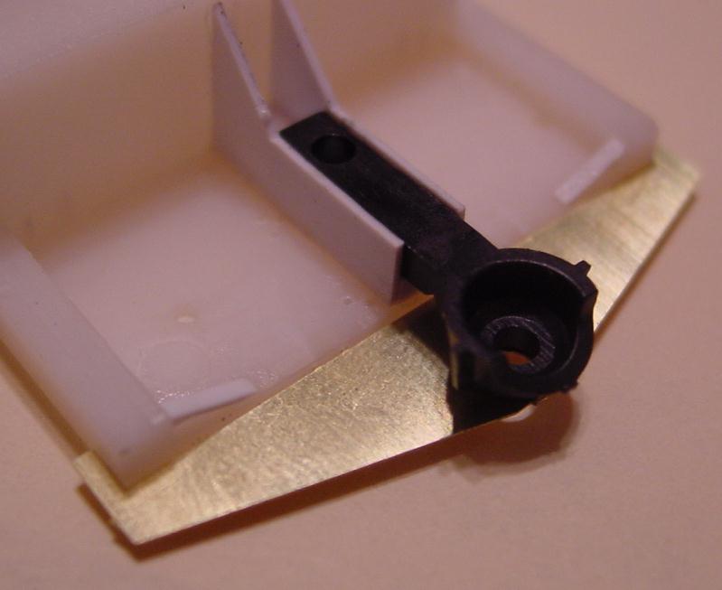
The female articulated joint does not have any kind of pin to help line it up. It is a visual alignment and isn't that hard.
I guess you could put a toothpick or something else through the holes to help keep everything lined up while you glued it together. |
 |
 |
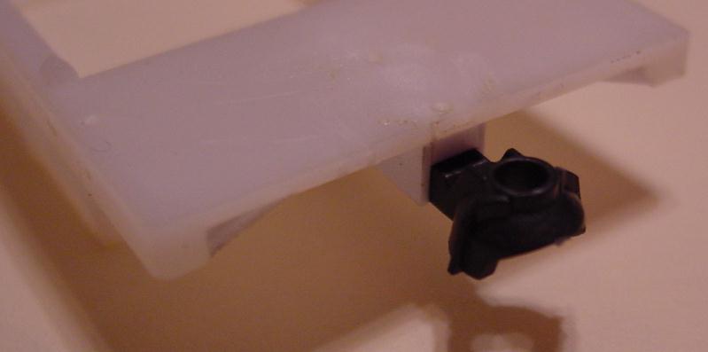
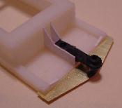
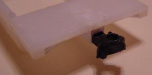
Here are a couple shots of the male articulated joint installed |
 |
 |
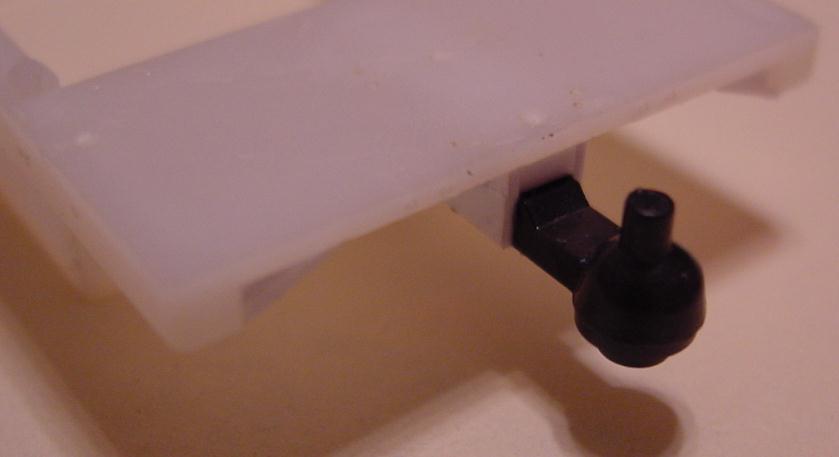
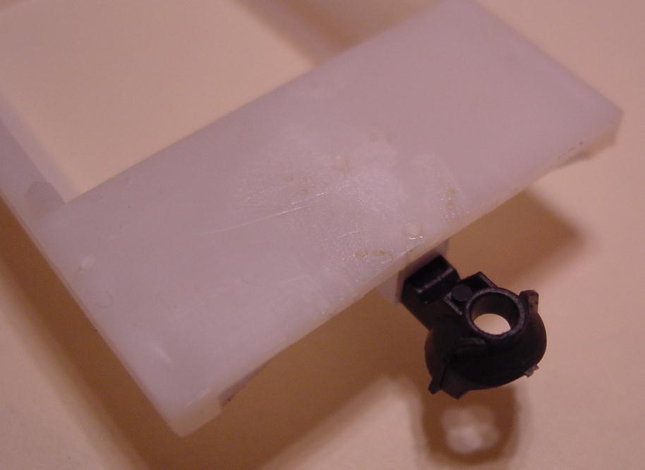
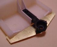
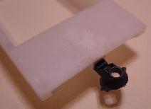
And a couple of the female articulated joint installed. I was considering drill a couple small holes and running some brass wire
through it to make sure the joints didn't pull lose under load. But hopefully lots of MEK will take care of that worry. |
 |
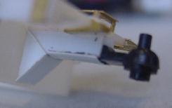 |
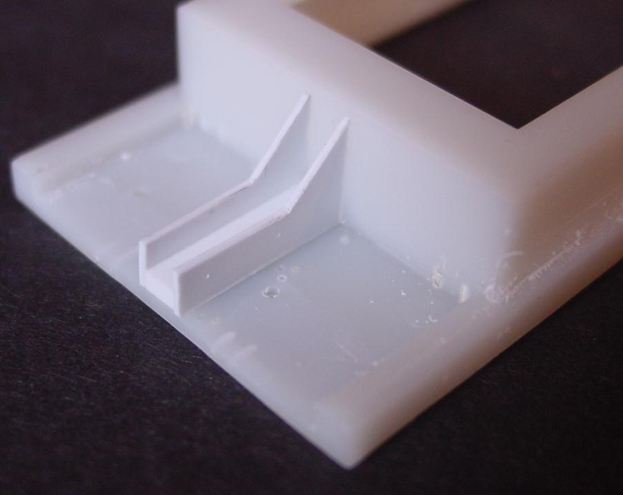
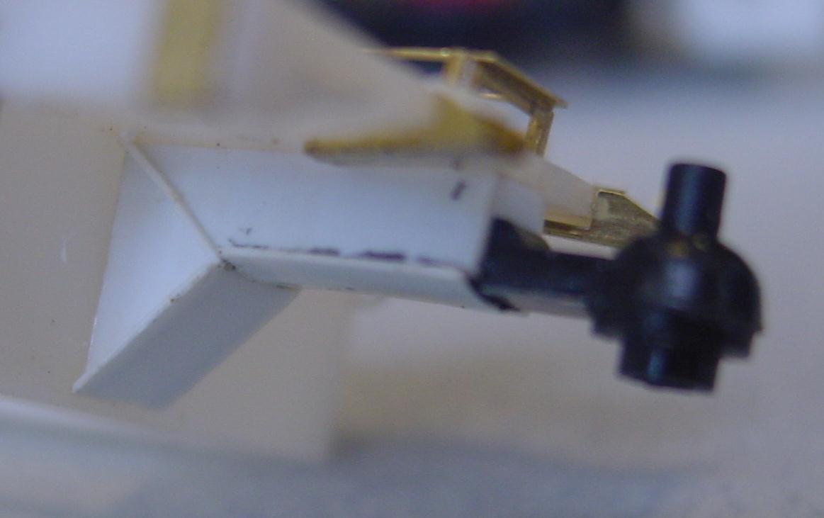
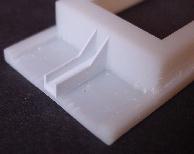
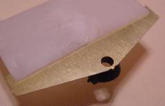
Jumping ahead here since I don't have any photos ready, here is a shot of one of the ends finished up. A couple pieces of .020"
styrene capped of the box. I don't remember where I saw the photo but some where I saw where there was a diagonal web on the bolster side. So I just cut a piece
of .020 X .020 styrene strip to fit and glued it in place. Hopefully I come across the photo again so I can prove I am not just making up details. |
|
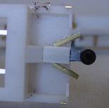 |
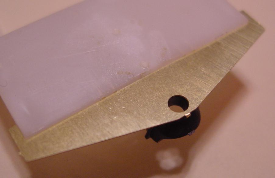
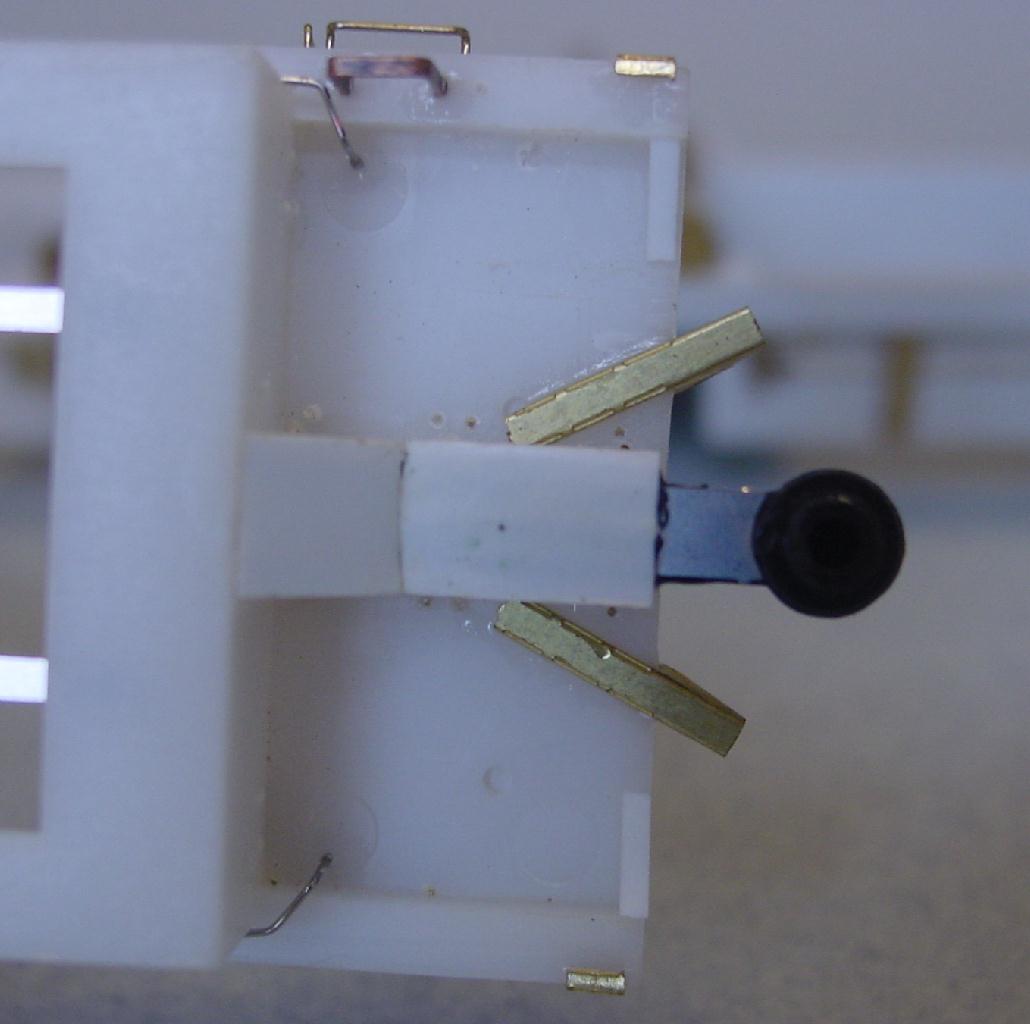
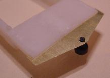
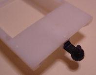
A couple things in this photo. Those end holes drilled to hold the alignment fixture and stabilizer arms, here is a bottom view of a couple
of those stabilizer arms installed. They have mounting pins to hold them in place. Do they need to be that long? Don't know but I wanted to make sure they stayed in place.
Also, if you look between the bolster box and the round articulated joint you can see a piece of stainless. I thought this might help stiffen the arm up and prevent
possible sag in the future. Don't know if it is worth it but I did it anyway. |
|