A few notes to keep in mind while adding these to your model.
| How to photos | How to description |
|---|---|
|
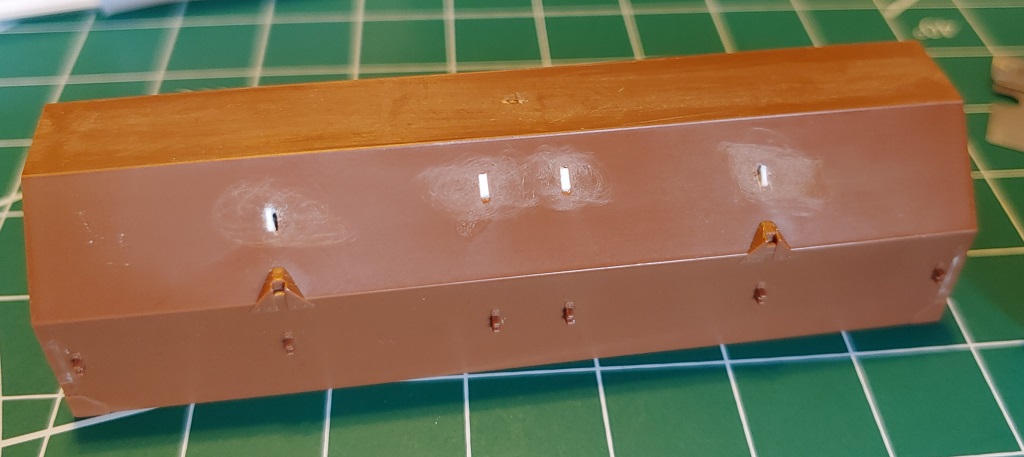
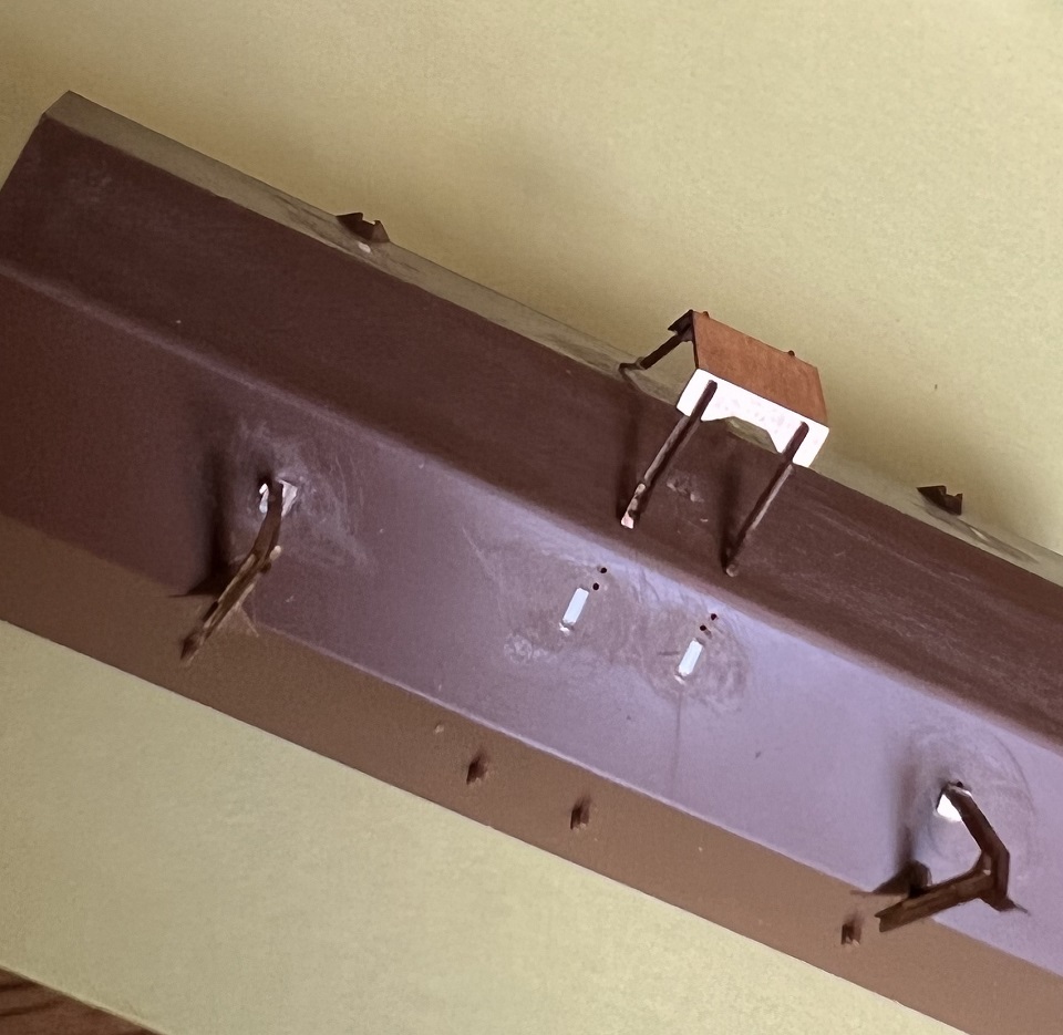
Yeah, I know, no one else still has undecorated Coil car kits they are going to be working on. But these will
help show contrasting colors of where the old parts mounted. You will be adding these new brackets there.
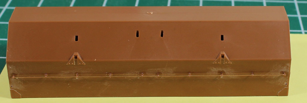
Assume you are replacing long ago bent or broken brackets, trim off any of the old brackets to leave a smooth
surface for mounting. On the hood sides
you see the triangular brackets. The closer you can trim them off to look like the area in the photo the better.
These new brackets fit best flush on the side of the hood. And the gap in the left hand fill spot? the new brackets will
insert into holes on the inside edge of these mounting locations. |
|
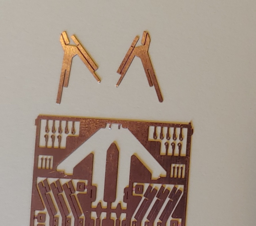
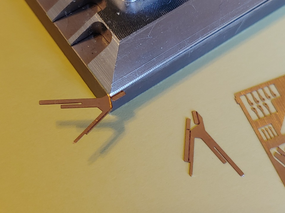
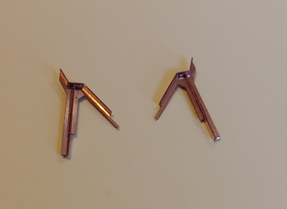
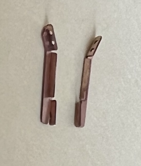
Starting with the hood stacking brackets, this kit contains four left and four right hand stacking brackets. The photo shows one of each. The only difference is the way the "angle iron shape" of the angled bracket faces. That will be pointing to the ends of the hood. In this photo the one on the left is the right and the one on the right is the left. I know I know. Gotta keep ya on your toes. |
|
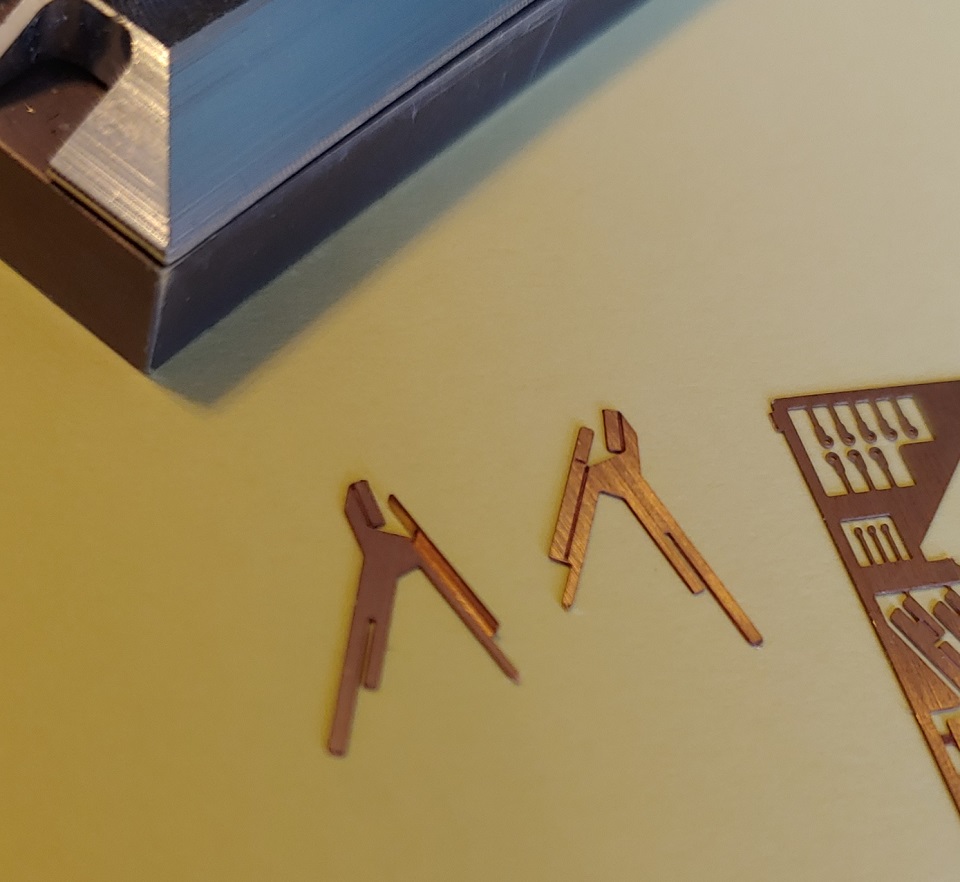
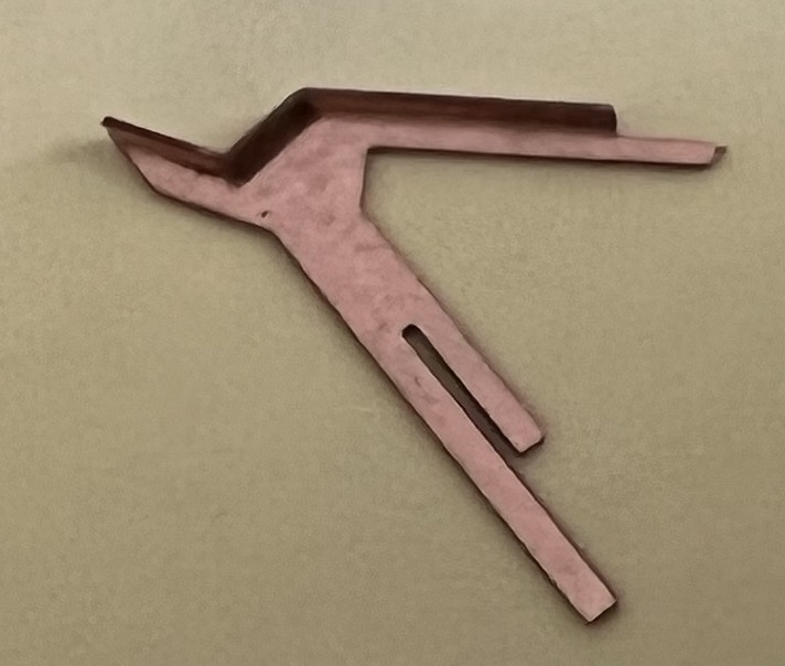
In the top photo to the left you can see the first bend of a right hand bracket has been made. You can use tweezers or small flat pliers to make this bend. I used a photo-etch bending tool like this for bends over a 1/4". It takes a little time to get use to using it but it does a good job of getting bends square and straight. Back to the bend. Bend this entire length up 90 degrees, forming an angle iron shape. That little tab sticking out into no where, use a pair of pointy tweezers to bend it down until it is even with the adjacent edge of the bracket. You can see it in the second photo to the left. These bends should be done in this order. If instead you bend the next section first, the tab you just bent over won't easily bend down into place. |
|
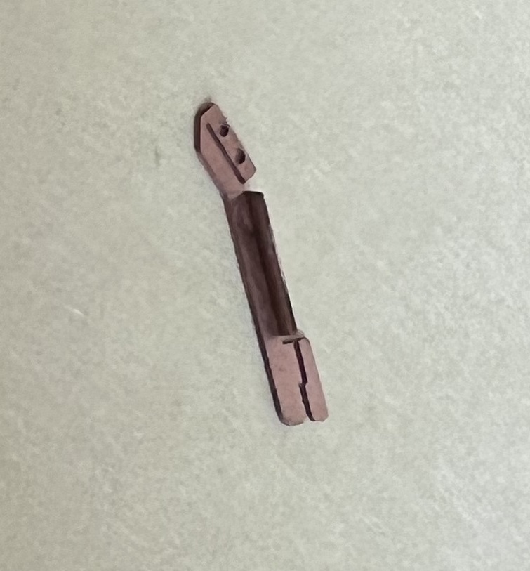
So you probably wouldn't need a bending tool to make this next bend, but the photo does a good job of showing what the next bend will be. Bend this little section up 90 degrees. The bottom edge of this sections rests against the tab previously bent, holding it down in place. No gluing yet. Also note in the second photo to left, the vertical leg has a slit in it about half way up. |
|
/
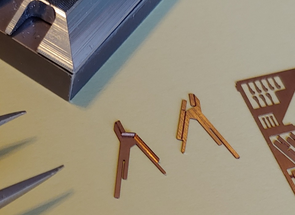
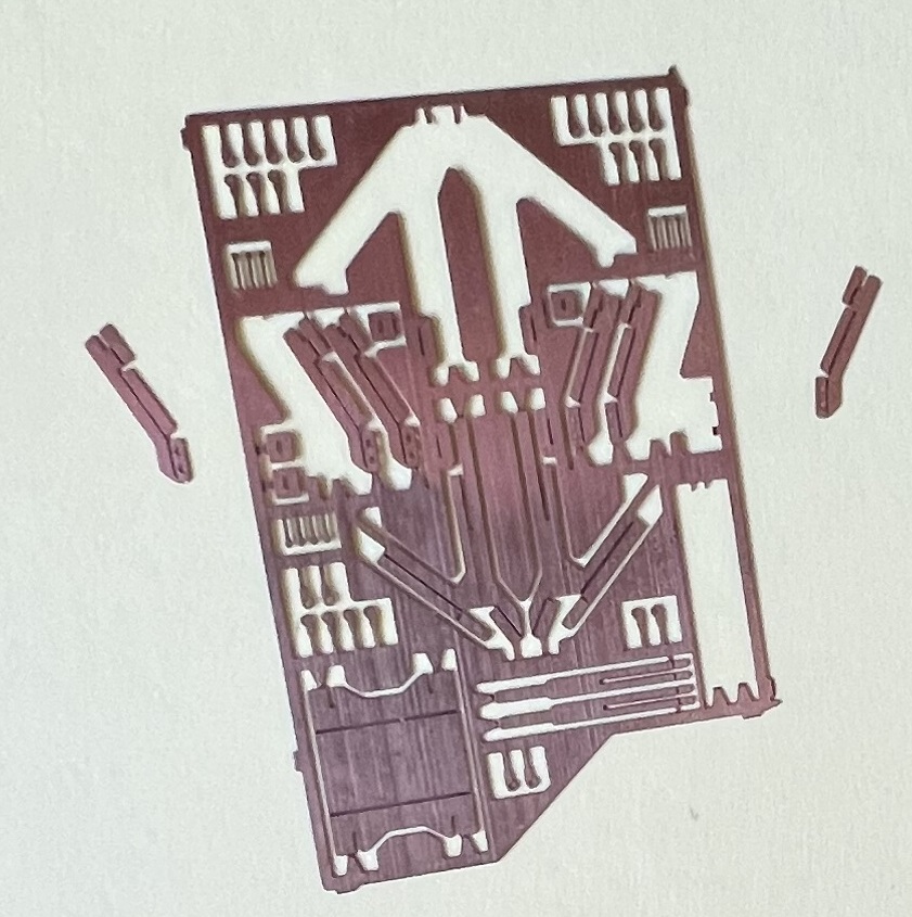
Back to the parts fret you will find there are eight flat stiffener bars, also with slits in them. Guess you know where these will go. A couple things before you get all excited and start sliding slots together. Depending on the etch process and how well these were etched, they may be a little tight. They were designed to be snug so they wouldn't flop side to side. You may need to CAREFULLY run a razor blade or hobby knife down the slits to clean them out slightly. Just letting you know so you don't start forcing them together and deform your bracket. Also, at the very top of the stiffener you will notice there are bend lines so you can bend the top section over 90 degrees (lower photo). These are ONLY used to help keep this stiffener at 90 degrees to the main bracket. You can remove them if you don't like them. One might be visible once in place. You can remove it if not wanted. They are small so you may not even see them, It is up to you. |
|
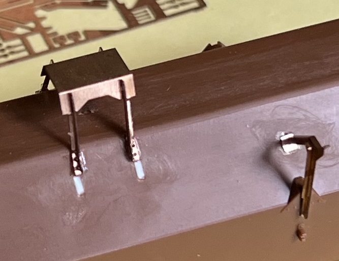
When installing the stiffeners, slide them up until to top rests against the horizontal bottom surface of the tab. The little bent sections of the stiffener should point toward the angled section. The bottom of the stiffener should be even with the longest leg of the bracket. Really shouldn't need to glue these together but a small dab of CA can be added to the joining point if you want. In the lower photo to the left you can see one right hand bracket(on the left) and one left hand bracket(on the right). They are designed where the sides you see here point to / face the ends of the hood. If your prototype is different(?) just flip them left to right. Hopefully this has all made sense so far. By the time you have assembled all eight (four right and four left) you are doing fine and ready to keep going. |
|
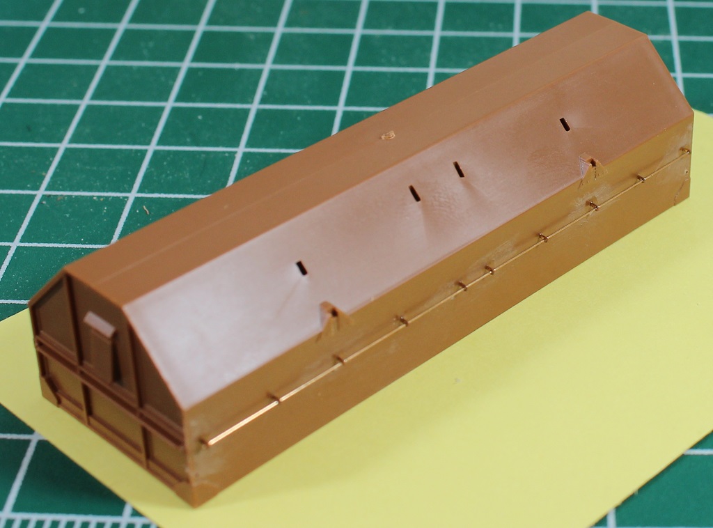
Prep the hoods for accepting the new brackets if you didn't while doing the stacking bracket holes. Small pieces of styrene strips could be used. OR slice off the plastic brackets flush with the hood sides. |
|
|
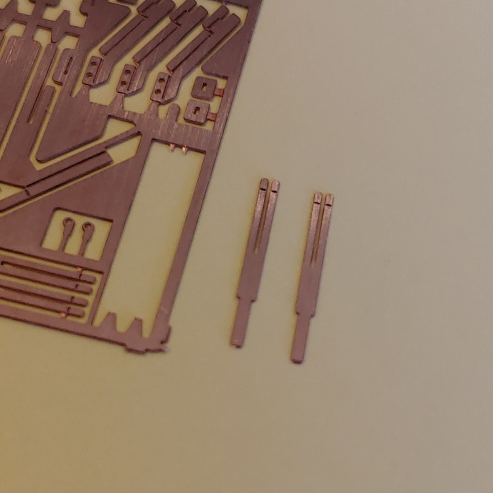
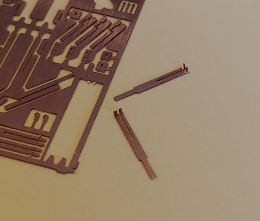
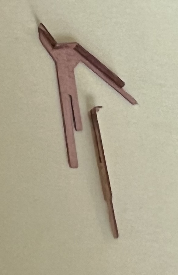
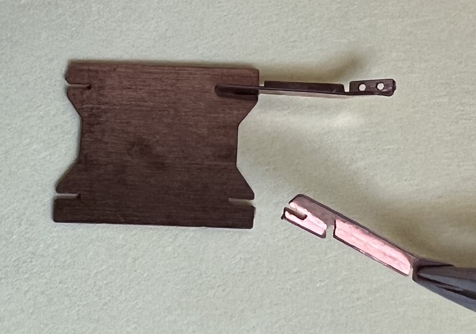
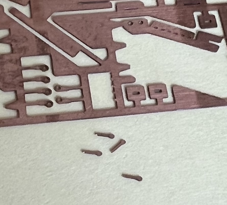
Here are two of the four lift bracket legs removed from the fret. Again there is a left and right leg. Suggest predrilling the two holes in each leg with a #78 drill bit. They should accept the NBW pins but Just in case they are tight... |
|
Use your bending tool of choice to bend the long center section up 90 degrees. |
|
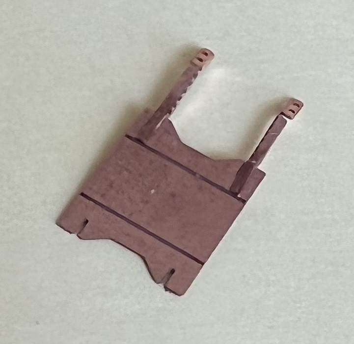
The bottom portion, the one with the holes, also bends up 90 degrees. The top section also bends up 90 degrees but notice it is offset to leave a gap in the bracket legs. |


|
There are two bend lines in the bottom surface of the lift bracket plate. Remove plate from the fret and clean up edges if needed where it was connected to fret. At the bend lines bend the outer sections up about 60 degrees. This is an estimate and may need to be adjusted once the legs are added. |
|
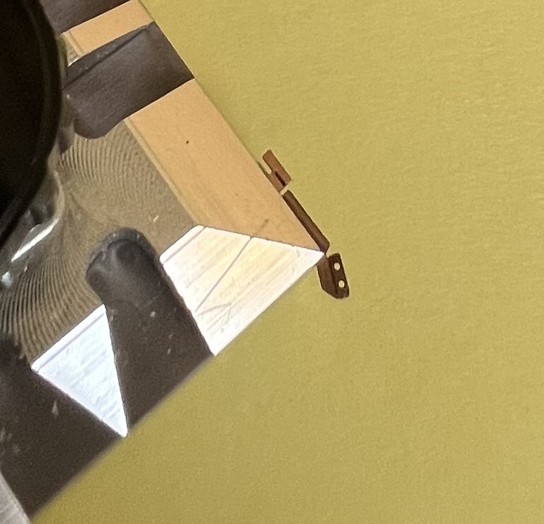
That offset slot at the top of each leg slides into a slot in the sides of the lift plate (not formed here for ease of viewing). The flat parts slide up on the back side of plate until it meets the fold. The angle iron shape sticks out 90 degrees from the top of the plate and face away from each other. A dab of CA on the inside should hold these in place. You could also use epoxy or solder them together. OR if you are not in a hurry, JB Weld would probably work too. |
|
So far I have not come up with a really good way to accurately drill for the mounting "NBW" pins. Once you are done adjusting the legs and have them glued to the lift plate, sit the assembly on the hood where you will want it. Add a very small dab of CA to each mating point to hold it in place. Now mark the bottom hole of each leg creating a drill point with a sharp pin. Chances are the assembly may come loose while marking the holes. Marking and drill one each will allow you to get at least one pin in each leg. Yes I have all the holes drilled. It can be done but holding and drilling them all at one time is just another test of abilities and patience. |
|
And yes, those tiny little pins are small! So only having to hold and hit one moving target might be an advantage. Insert and CA a pin in the bottom hole of each leg, one leg at a time. Once the first four are done, it will be easier to redrill and insert the remaining pins. I believe using these metal pins will add strength to the mounting and hopefully help keep the new bracket in place. |
|
So That should pretty much conclude the instruction portion of adding our Stacking and Lifting Brackets to your coil car hoods. Again, updates and tweaks are planned as
needed. |