Steel Coil Car Stirrup Steps and Coupler Cut Bar Hanger brackets
Here are the preliminary / first draft of the instructions for adding our Stirrup Steps and Cut Bar Hangers to the Walthers Steel Coil Car models. May make some tweaks
to them but hopefully they make since and are useable to add these parts.
These instructions are only available here online. If you need / want to save or print a copy, you should be able from your browser tool bar.
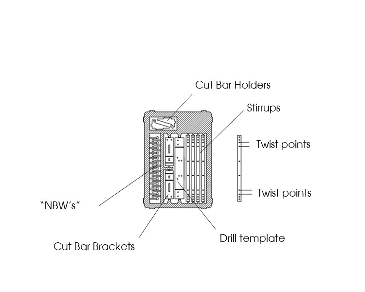
The kit contains 4 stirrups that will need to be bent / formed to shape, 2 hanger brackets that will also need to be
bent and assembled and a drill template to aid in properly locating the steps, hangers and even grab irons (not
include) in the kit.
| How to photos | How to description |
|---|---|
|
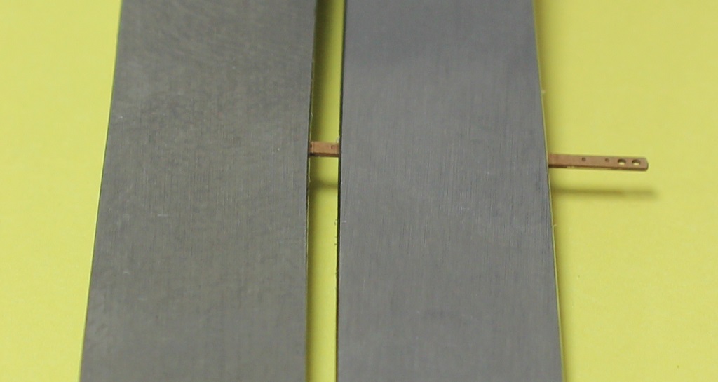
As you can see in the diagram above, there are "twist points" on these stirrup step strips. This allows them to bend 90 degrees with less risk of them breaking in half. The top photo to left shows a strip positioned between the handle ends of two sets of tweezers (other tools can be used). Holding at these points and twisting 90 degrees will form the mounting points at 90 to step. The other photo shows four steps in different forms and the progression of the four steps to form each stirrup steps. Twist each end and bend step to shape at center points. The two little dimples in the center are the bend points to form the stirrup steps. Also, it is suggested to pre drill the holes in the ends of the stirrup strips and hanger brackets. They should be open enough, but etch process vary and the holes may be a little small. Easier to do it now if needed. |
|
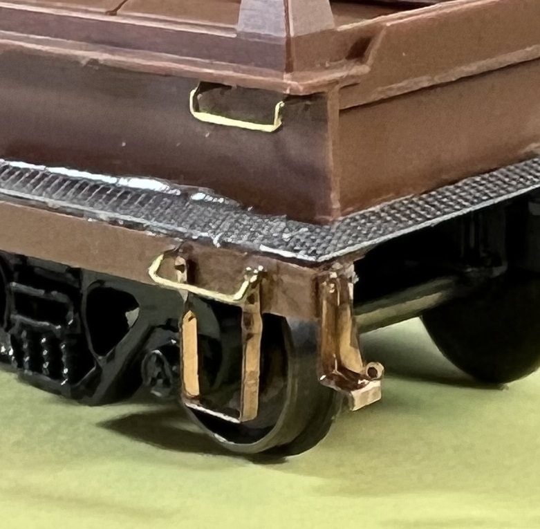
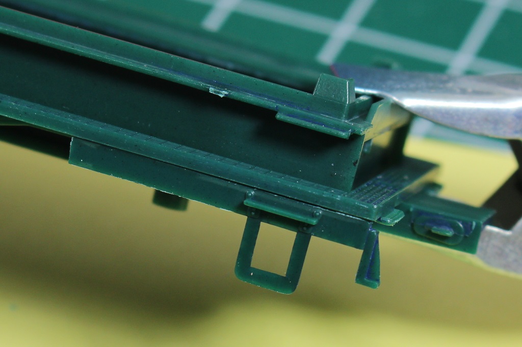
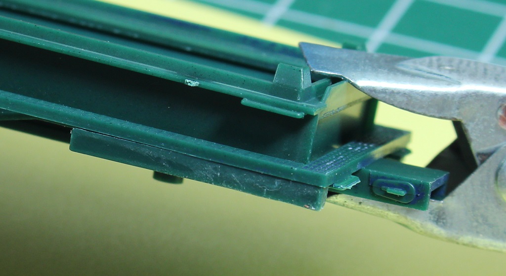
Depending on whether you are (finally) building a kit or reworking a car you have had in service for years, you will need to remove the details on the sides of the frame. The top photo shows what the sides look(ed) like and the bottom shows all the parts removed. Assuming you will be replacing the grab irons, remove them as well. And yes, This would be a great time to replace that plastic walkway if you haven't already with one of ours. |
|
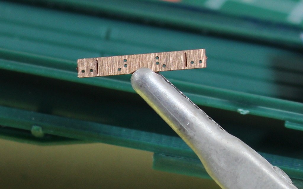
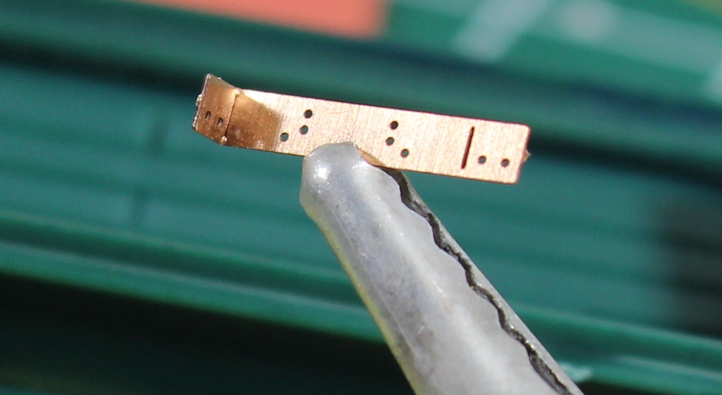
Another good reason to remove all the details off the side frame is it is easier to use our supplied (tiny) drill template. This template has a right and left direction as well as a top and bottom. This one is being held upside down. Turns out this is a good highlight to make sure you pay attention to which side you are doing first. The bottom photo is the template bent to be used on the left corner ( as viewing car side). the two pair of two holes should be on the lower part as seen in next photo below. |
|
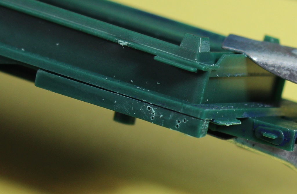
depending on what works for you, place the template on the corner of the side frame and mark where to drill the needed holes with a sharp pin or a drill pilot hole. Suggest bending and marking holes for right corners with cut bar hangers first. Didn't think this clear through but the bent over hanger bracket template will need to be unbent so the left side section can be bent for drilling left hand side frame. The left hand frame does not need the end holes for the hanger brackets, just the stirrup and grab iron holes. |
|
OK, time to mount the stirrups steps with some of those TINY "NBW" pins. If you are REALLY patient and have steady hands, hold the stirrup over the side frame, insert a pin in each hole and CA everything together. OR, I find is easier to insert ONE pin in the bottom hole of one leg and CA in place making sure the holes in other leg are close to lining up. Then insert another pin in the bottom hole of the other leg and CA in place. This should keep the stirrup in place. Re-drill the top holes (they may have collected some CA) and then insert pins in the top hole of both legs. Found this method to be less stressful. Did I mention those pins are tiny? |
|
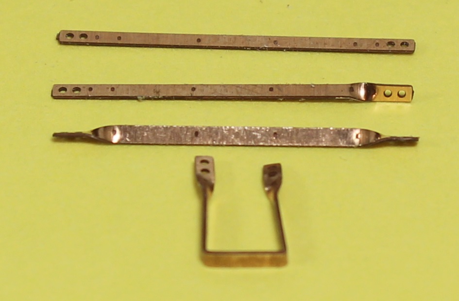
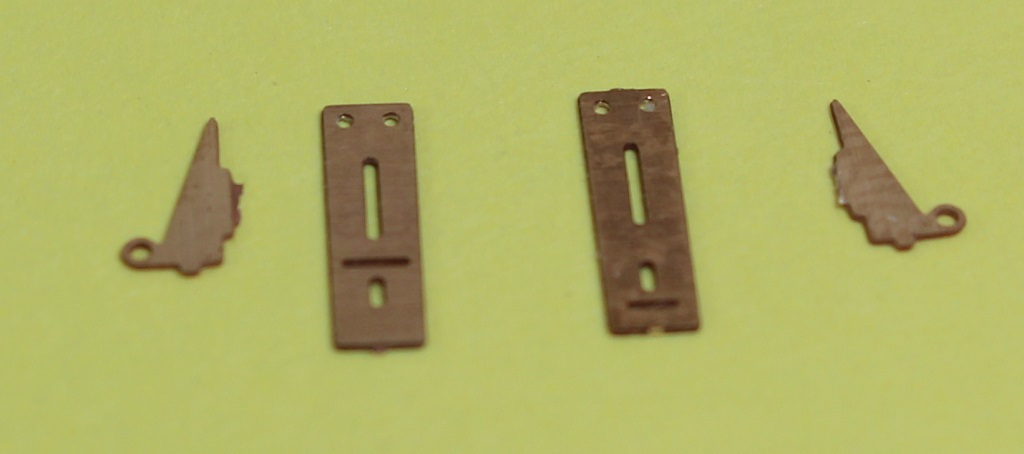
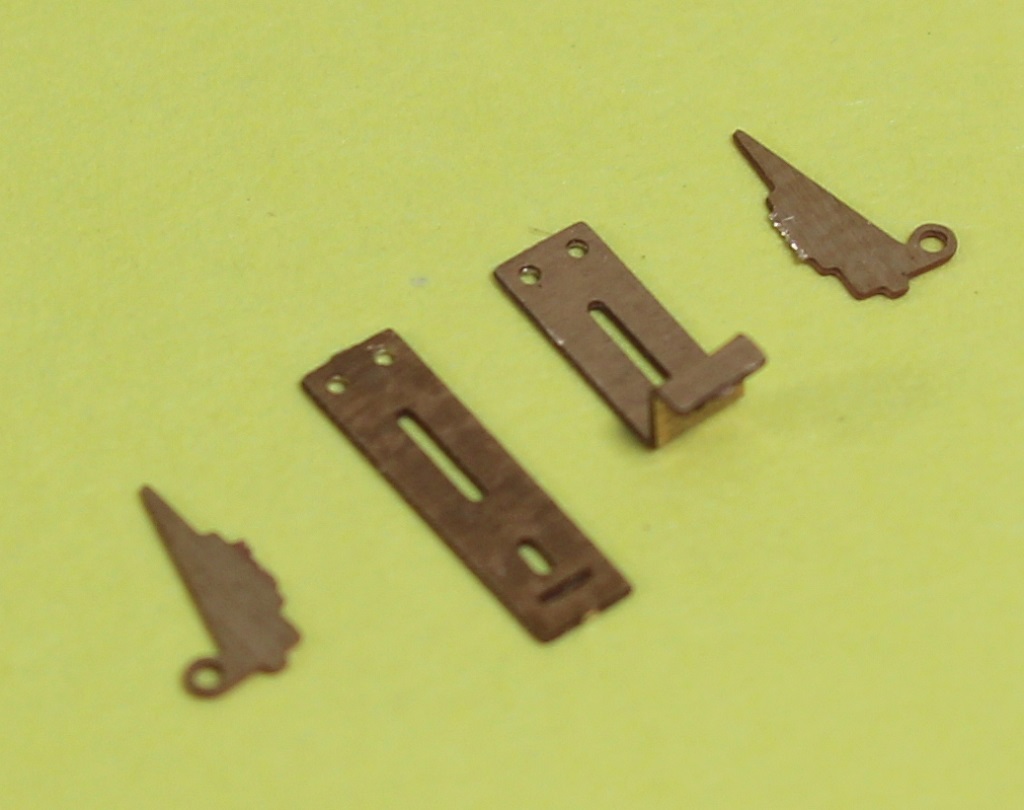
Here are the four parts used to make the two Coupler cut bar hanger brackets. The center two parts are the hanger brackets and you will notice there is front and a back to these. There is a bend line on both sides. The left bracket is the front surface and has a bend line in about the middle. The right bracket is the back surface and has a bend line out toward the end. This is the first bend to make - small and easier to hold. Bend it 90 degrees and then turn over and bend 90 degrees the other line. The bottom photo shows a bracket bent to shape. |
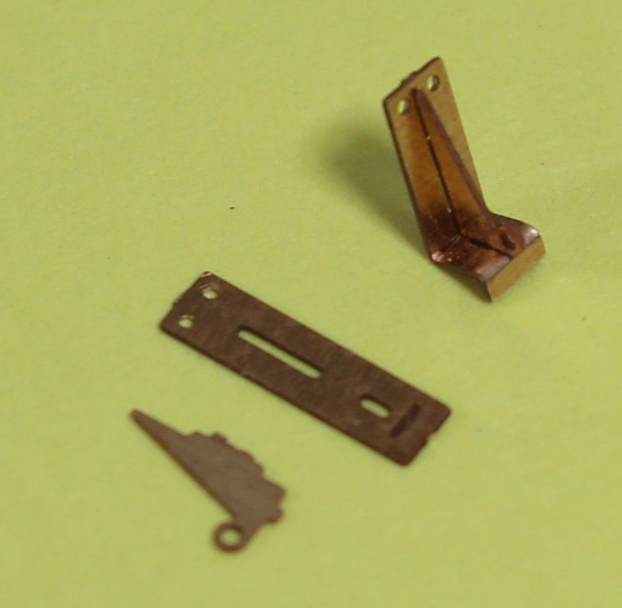
|
There are tabs on two of the edges of the Cut bar holder parts. These tabs fit in the slots in the center of the brackets. Position holder on bracket as shown and CA assembly together. |
|
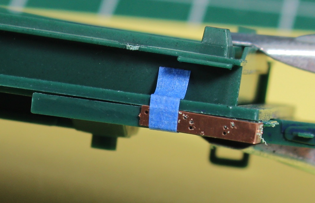
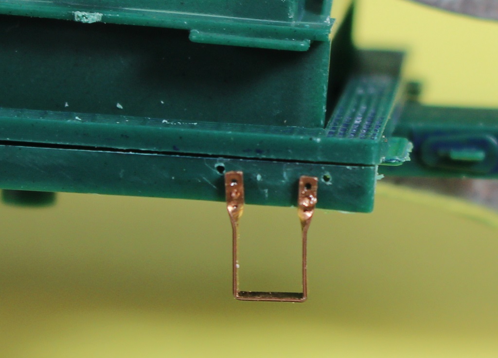
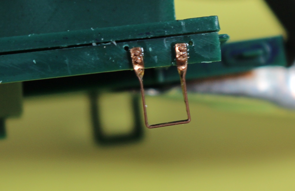
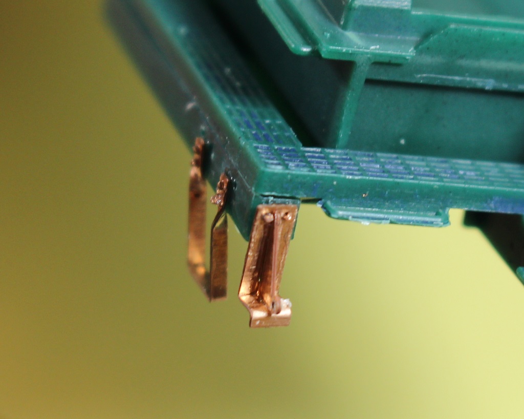
Mounting the cut bar hanger bracket assemblies on the ends of the right side frame can be accomplished by inserting a couple pins in the holes of the brackets and drilled holes and
CA in place. If doing one pin at a time, make sure it stays square and the other hole lines up. Repeat on the remaining corners, |