Disclaimer - While my intension are to have well-organized pages for each of my cf 2970 detailing projects, this page will have to do for now. I admit I was trying to do too many models at one time and got ahead of myself at times. I do plan to go back and redo this page, but after the 2015 St.Louis RPM meet unveiling, I wanted to have something out there so others could see what I have done so far and how. Your patience and understanding is appreciated. I am just trying to have fun and share my modeling adventures with others.
This page has information about modeling three variations of CF2970 covered hoppers. Parts of it can be used to model any one of the three. If there is information pertaining to one specific variation, I have placed a series# in front of the description text. At some point I will separate these pages. Thank you again for your patience!
Modeling CNW 96748 ACF 2970cf covered hopper
CNW series 96620 - 96769 150 carsbuilt Aug./Sept. 1966
Modeling CNW 96811 ACF 2970cf covered hopper
CNW series 96800 - 96813 14 carsbuilt June 1969
Modeling CNW 175169 ACF 2970cf covered hopper
CNW series 175000 - 175299 300 carsbuilt Oct./Nov. 1967
Here are some notes of various details I see on the 96620 series of cars.
Here are some notes of various details I see on the 96800 series of cars. I have only found three photos of these cars online.
Here are some notes of various details I see on the 175000 series of cars.
| How to photos | How to description |
|---|---|
|
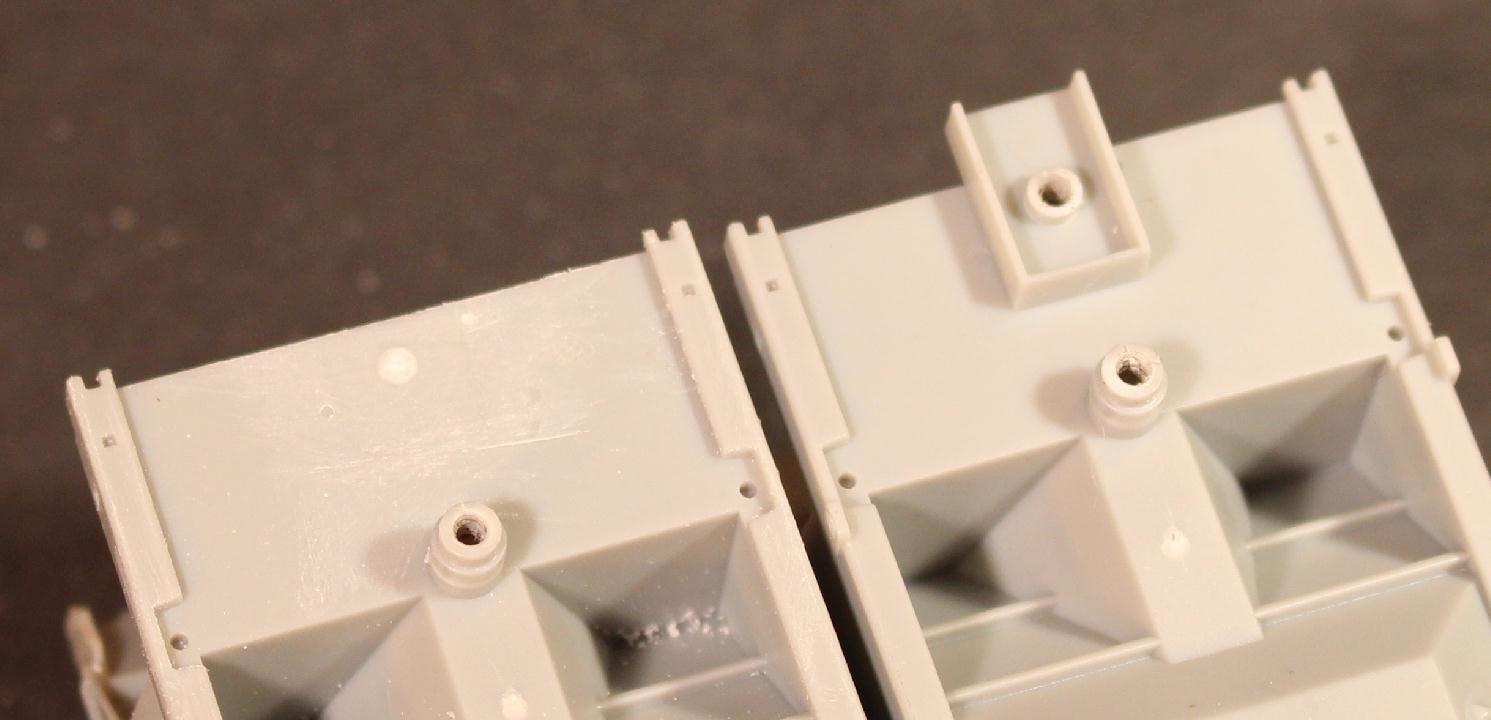
Just like the other ACF covered hoppers I am working on, the first thing I am doing is removing any unneeded details from the body of the model. The couple boxes will be replaced with Draft Gear boxes from Moloco. The original boxes were removed with my small mill. The car end floor that the original box was cast on to is nice and thin. But this makes the milling work a little harder as the floor would flex as the mill bit moved over the box. A piece of brass tubing 'clamped' to the floor helped a little bit, but I need to get better at clamping items in the mill to hold them in place. |

|
Here you can see the coupler box has been removed and a Moloco draft gear box sitting in its place. For comparison an unmodified body is sitting next to the modified body. The new box is only sitting in place for this photo and will be mounted later. It will need to be measured and shimmed for correct Kadee #158 coupler height and also to make sure it is correct for length over striker plate (box end face). The bolster is also modified to make room for the new draft gear box. Modified bolster on the right. |

|
96800 - Since this series of cars did not have the normal shaker pockets on the sides of the bays, I carefully removed the cast on pockets. These actually sliced off pretty well with a razor blade. Then a little sanding to smooth the area out. Also removed the rope pull tabs on the lower edge of the side sills. |
|
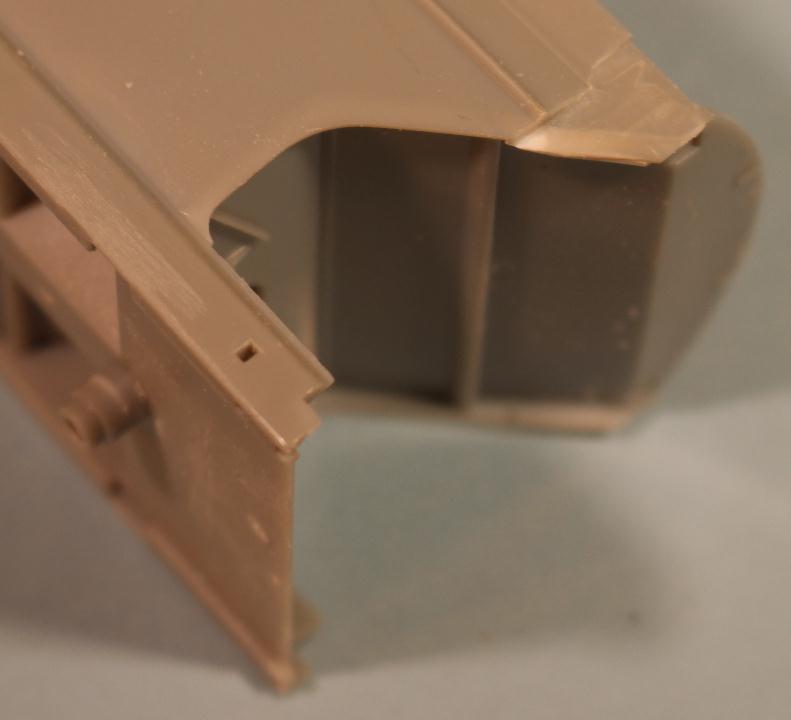
96620 - One of the things you notice about this unique series of cars, other than the high brake wheel and tall side ladder, is the upper body cutout to clear the tall side ladder. While the B end ladder is the only one to need this cutout, they also made it on the A end. I used a mill to make this modification. A little styrene was needed to thicken part of the wall up as it got too thin. |

|
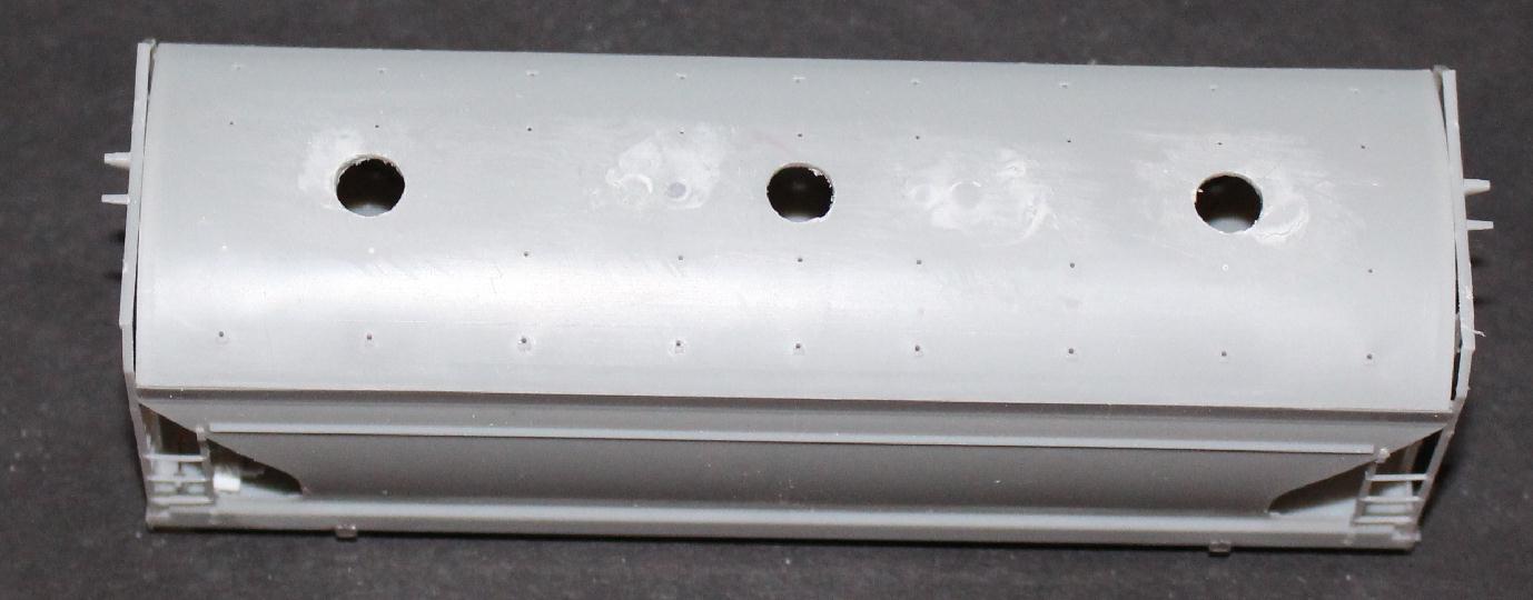
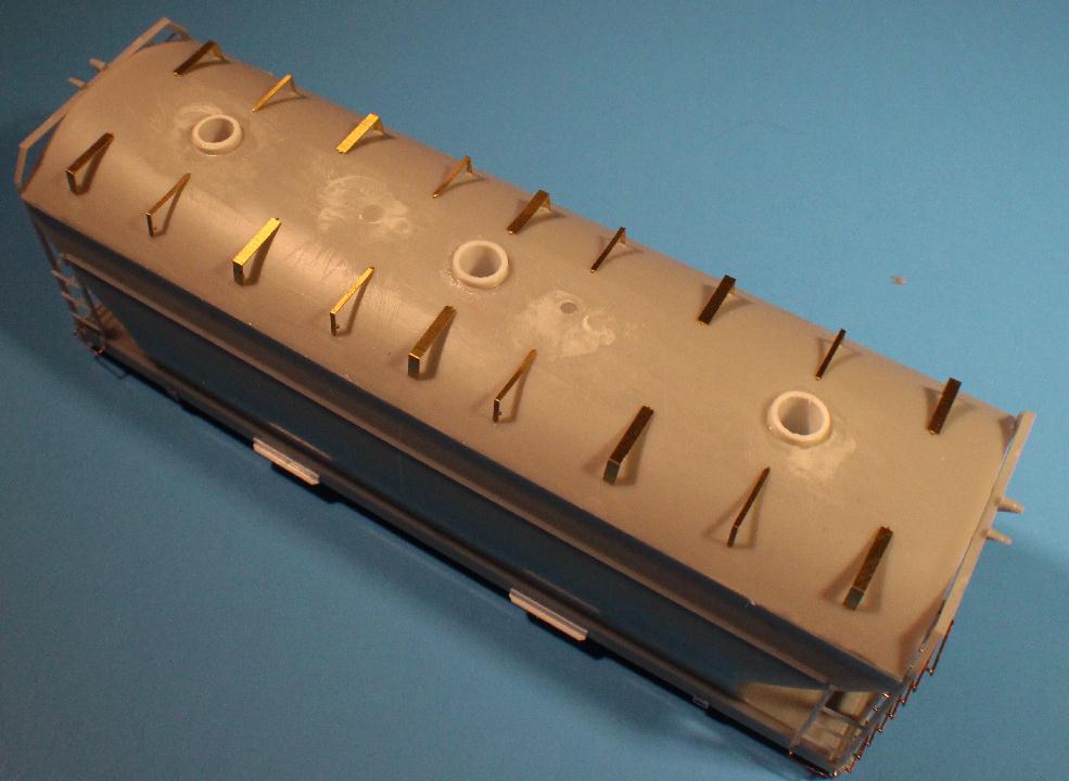
96800 - Moving to the roof, the Athearn model is set up to have four 30" roof hatches. Since I will have three 20" hatches I needed to fill the holes for the 30" hatches. The larger hole is about .100" and I have ample material about that size laying around. I use a 1/8" drill bit and ever so slightly chamfered the holes in the roof. Then using a small piece of sprue, I MEK'd the rounded end to the chamfered hole. The MEK melted the two together and a little pressure made sure all voids were filled. After everything set and dried, the excess material was trimmed away and the roof smoothed out. |
|
96800 - What to use for the 20" hatch chute? So does a 20" or 30" hatch mean the cover or the opening in the roof? Of the four ACF car projects I am working on, three of the models come with 30" hatches and all three are different sizes. Anyway, I will be using Atlas hatches from their CF5701 car for this project. And to mount them I will use small pieces of 1/4" styrene tubing. The prototype hatches are spaced 11'6.5" inches apart. So one .250" hole in the center of the roof and one to each side of that hole, 1.593" away. |

|
96800 - A small piece of the Evergreen styrene tubing is inserted into the hole. I left about .030" sticking out. Don't know if that is correct but for some reason, I feel this looks close. I will be using roof hatches from a Atlas CF5701 kit I have stashed away*. I carved off the stiffener ribs to give the hatches a flat look like those I have seen in photos. |

|
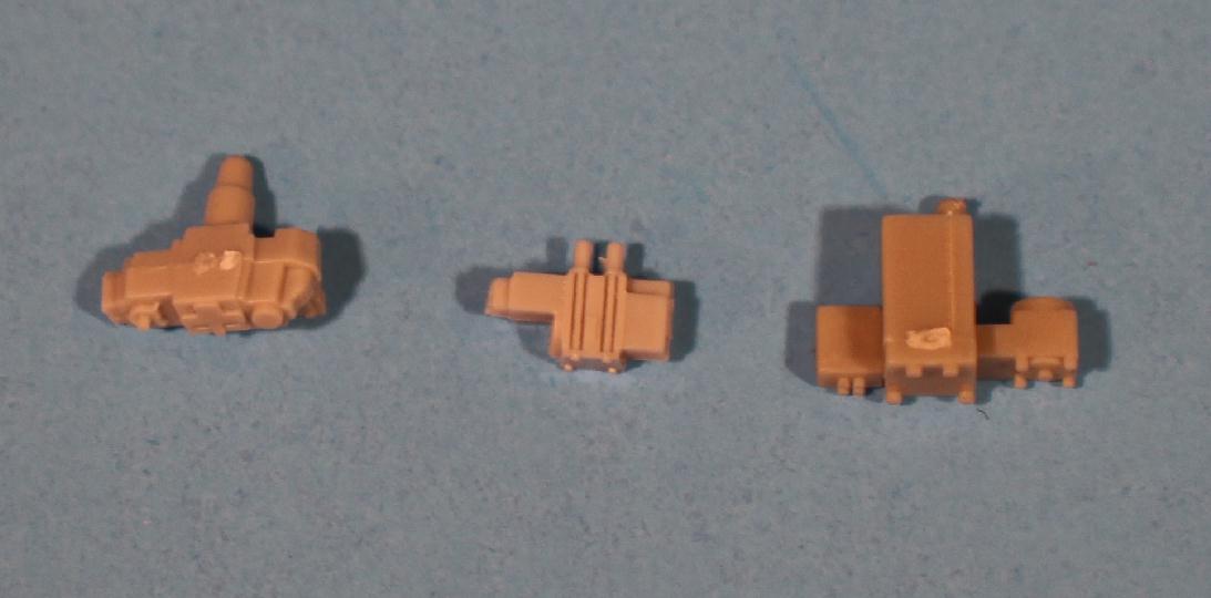
Moving to the B end of the car, I will be replacing the brake equipment supplied with the model with parts from Tangent. Athearn didn't spend a lot of time on detail for these parts. Nice overall model but scrimped on some small details. I know, the RTR masses are fine with it. I probably spent more time looking at and deciding on which brake reservoir to use then most operators do taking... - better not go there.... Anyway, this photo shows the four reservoirs I considered. From upper left in clockwise direction: InterMountain CF2980, Tangent PS4750, Tangent 4740 and Atlas 4650. |
|
Like the brake reservoir, I also decided to replace the AB valve supplied with the model. Here it boiled down to three alternatives and even those three didn't really thrill me. From left to right: InterMountain CF2980, Tangent 4750 and Atlas 4650 |


|
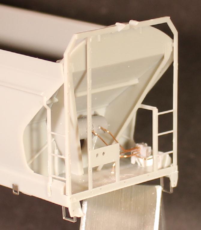
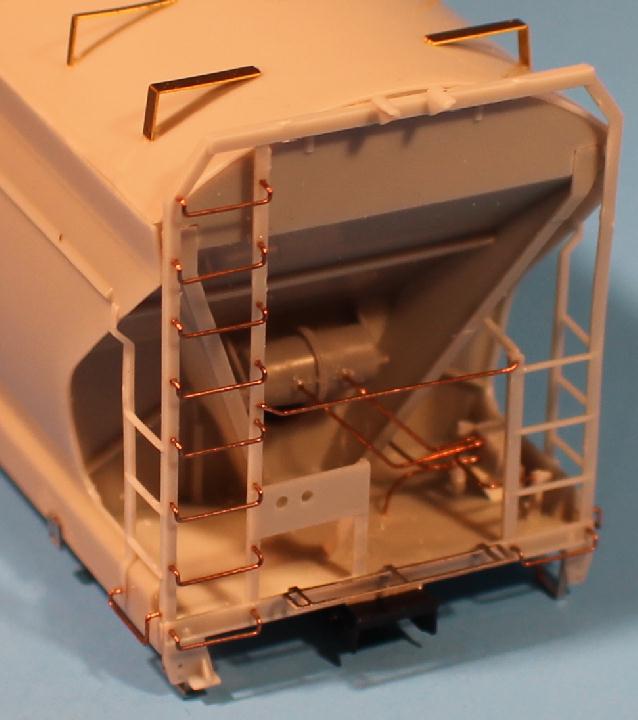
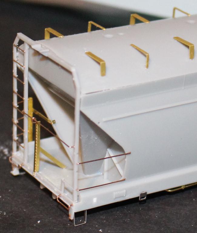
As you can see I choose the Tangent PS4740 reservoir and PS4750 Valve. ACF mounts their reservoirs up to the angled mounting brackets vs. down on like Pullman Standard. Also added the end slope sheets before going to work on the piping. This series of cars had truck mounted brake equipment, which means only the air reservoir and the AB valve are visible. So the only piping needed are two lines from the reservoir to the valve, one down to the air line, one back through the end wall and one to the retainer valve. A couple other small details I haven't been able to get a good photo of are the air trap and shut off valve I used from the Tangent 4750 detail sprue. Look close next to the AB valve. |

|
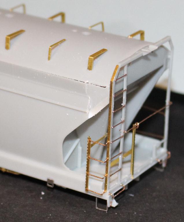
With all the brake equipment installed and complete, I could finally start adding the end cages. No modifications
needed on these, just MEK in place. I did add a small angle bracket to the back of the post for the brake housing
plate. This is just a piece of .010"X.030"X.300" styrene glued to the edge of .010"X.040"X.300" styrene. Trimmed to fit what
looked about right. |
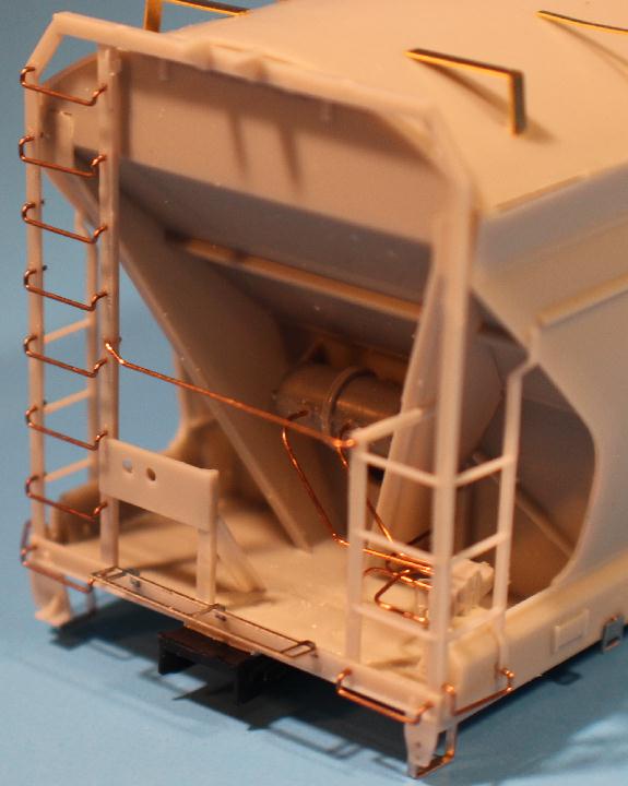
| The A end of the car is a lot quicker to put together. Just the end cage for now. No brake equipment to mess with. Side ladders just like the B end. I wanted to put these parts on earlier but refrained to avoid damaging them while doing other modifications. |
|
|
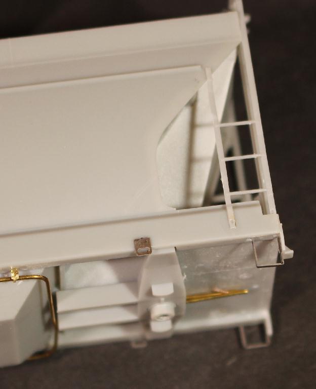
On the sides of the car there are a couple details to add. I am replacing the rope pull plates with stainless parts. Just wanted that thinner plate look. Probably could have made these out of .010 styrene strips. Would have been easier to glue on. These glue on with a metal pin inserted into a hole and CA'd in place. New stainless steel stirrup steps were added to the corners rather than the plastic one supplied with the kit. There is always that one corner with a broken stirrup step... |
|
I made all new grab irons out of .012" phos. bronze wire. Took a few attempts to get the hang of it. I am fine with the results. I have some of the metal grabs that Athearn supplies with the 2970 kits. Don't know what I was doing wrong but I could not get them to glue in place. The CA just wouldn't set up. These set instantly. Is there something about the CA and that metal react against each other? It was less work to make new ones then fight the metal ones.
|
|
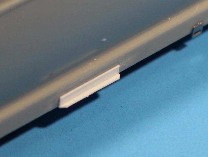
96800 - On the lower edge of the side sill there are some sort of angle brackets about the width of the bay. Not sure if this is some sort of shaker bracket or what. I made these by gluing a piece of .010X.060X.450 styrene strip to the side sill. And then a piece of .010X.040X.450 strip, chamfered outer corners, to the lower edge of the .060 strip, creating a .070X.040 angle bracket. Are they correct? Don't know but they look fine to me. And yes these could be made out of brass or stainless for strength purposes. But CNW only had 14 of these cars, in this series, so it isn't like I will be building more than one or two. |
|
On the bottom side of the car, rather than using the plastic train lines supplied with the kits, I made new ones out of .020 brass wire. Going to assume that the reason for train lines on both sides of the car has to do with truck mounted brake cylinders. The 2980 and 4600 cars I am working on have body mounted cylinders and a single train line. Both lines are the same and just mount inverted. Used my #10886 train line hangers to hang them from the bottom of the side sill. There is a hole provided in the bolster to hold the ends of the lines. |
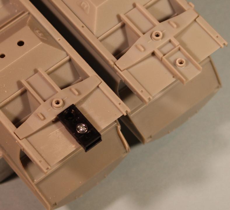
| It is time to add the Moloco draft gear boxes. Getting the new boxes centered isn't what concerns me, it is getting them the correct height. I assembled a box with a #158 Kadee and taped it to the bottom of the deck. Using the Athearn supplied trucks and wheels, I mounted them on the car and set car on a track to check the height. There is a little difference. A piece of .010" styrene between the deck bottom and coupler box to achieve an acceptable coupler height was needed. |
|
|
Using the reference material I have, the length of the car over the striker plates (coupler box face), the length of the car should be 5.095" (or 36' 11"). To find out the length I need to trim the Moloco boxes to, I measured the distance to the outer ends of the bolsters. That length was 3.885". Cutting two boxes to .605 each, once mounted I was at the 5.095" needed. My .010" styrene shim was the length of the area between the car and the box, about .520", as I didn't want the shim exposed. |
|
96620 Kind of got ahead of myself here. Got so involved in getting it all put together I forgot to take more photos. Will try to explain things in the next several photos. |
|
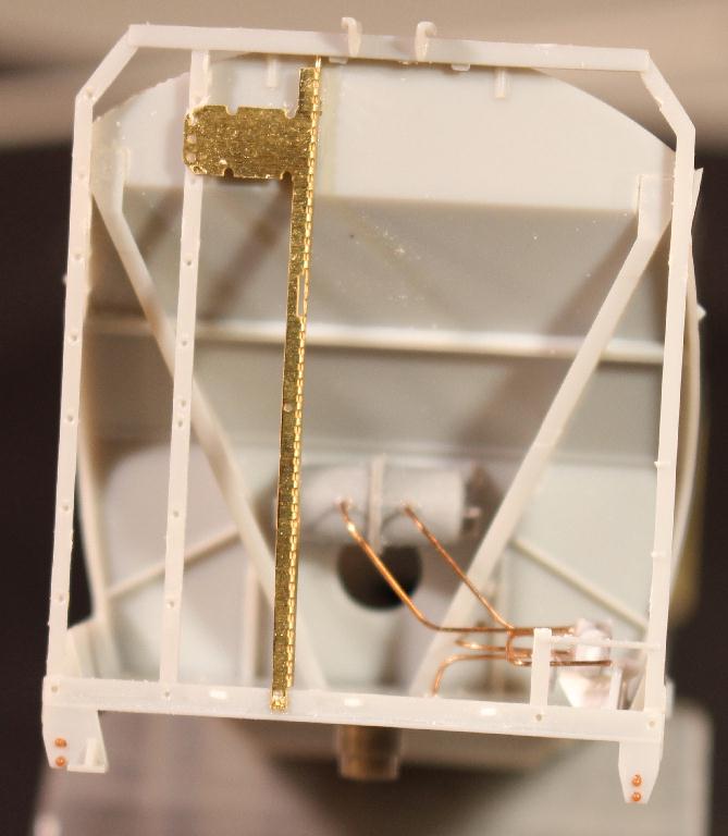
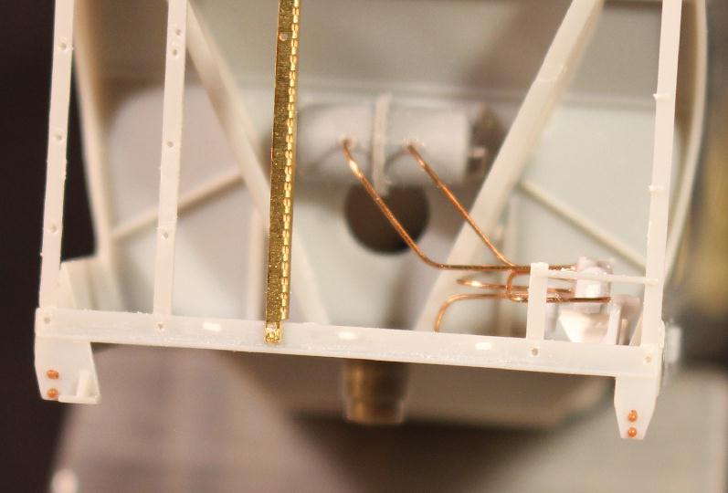
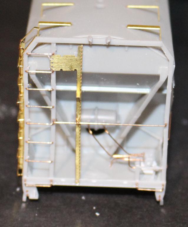
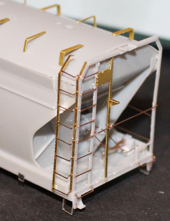
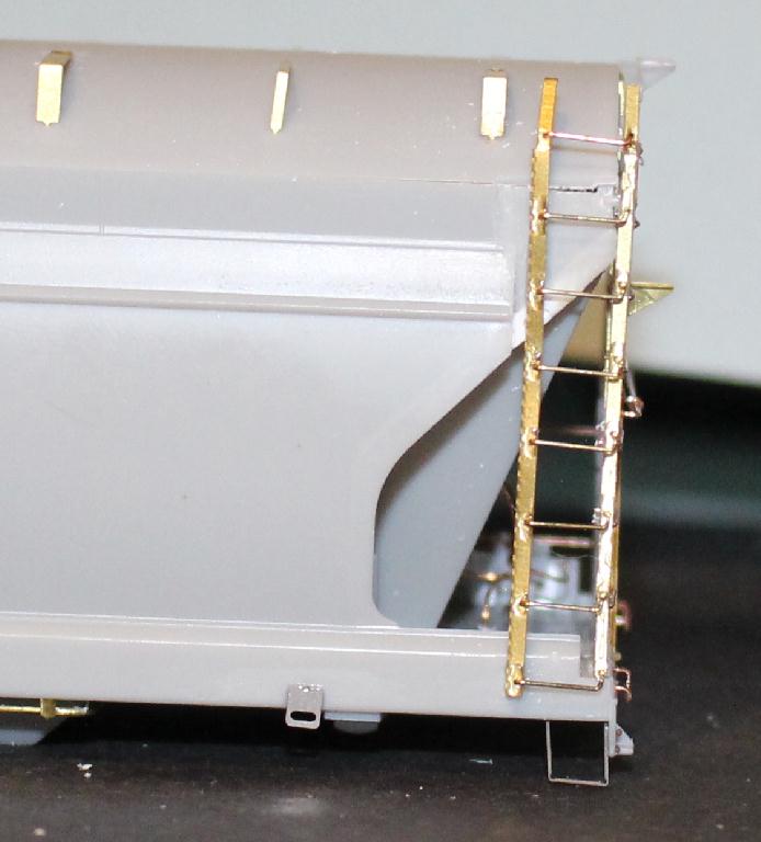
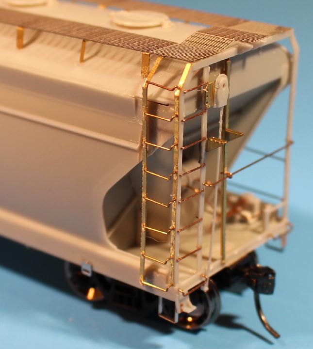
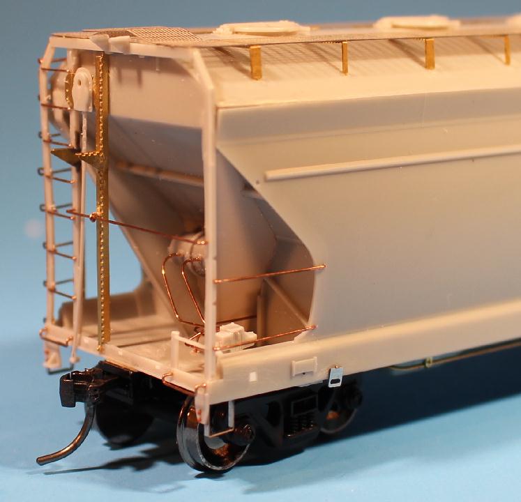
96620 Again I used the Athearn 'B' end frame but shortened the right hand ladder to one rung. Also removed the brake housing mounting plate and support, leaving just the tall ladder bracket. A new high mounted brake housing plate and support was etched and added in its place. The top has a mounting pin inserted into a hole hold in place. The lower end has an NBW through a hole to hold in place. These photos also show that I have started inserting NBWs in the holes in the corner brackets to appear as the stirrup step attachment bolts. |

|
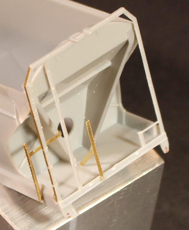
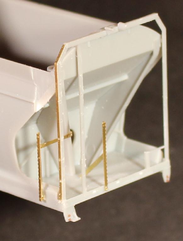
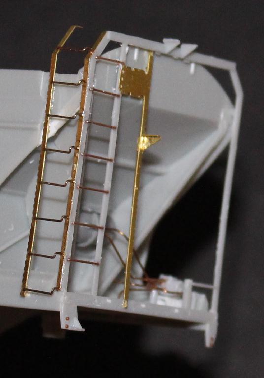
96620 OK, this where it got challenging and was part of the delay in my original design attempt. There are two different grab irons on these corners and neither one are like the ones used in the kit. As you can see, the end ladder grabs are straight vs. drop like the kit (and most CF2970s). And the side ladder has one drop end (not both ends) vs. straight like the plastic side ladder. I made all of the new grab irons out of .012 Phos. Bronze wire. |
|
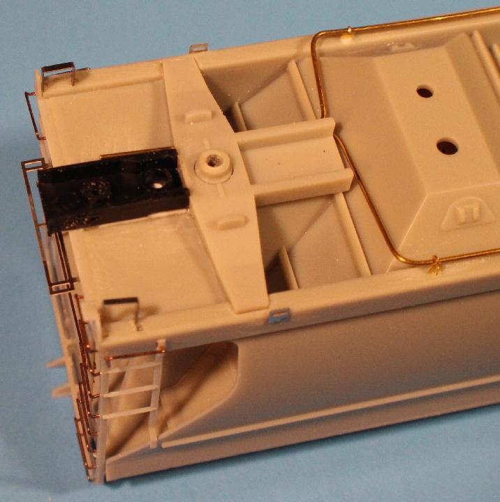
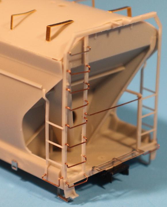
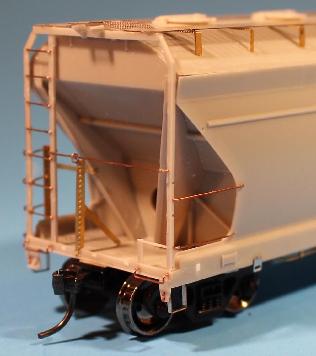
96620 There is a long grab across the end, kind of like the standard style but from the corner post instead of from the ladder post. There are also two long grabs on the opposite (left?) side rather than the side ladder. The side ladder mounting holes are filled on this side. Also filled the mounting holes that would have been used for the coupler crossover platform with pieces of .010 X .030 styrene strip. |
|
96620 The 'A' end gets the new long grabs like those described above. The lower side ladder mounting slot is not completely plugged where the new side ladders are added. I left a slight gap to insert a tab on the bottom of the new ladders into. Will try to get a photos on the next build... |
|
96620 Just a couple more photos 'cuz I had um'. |

|
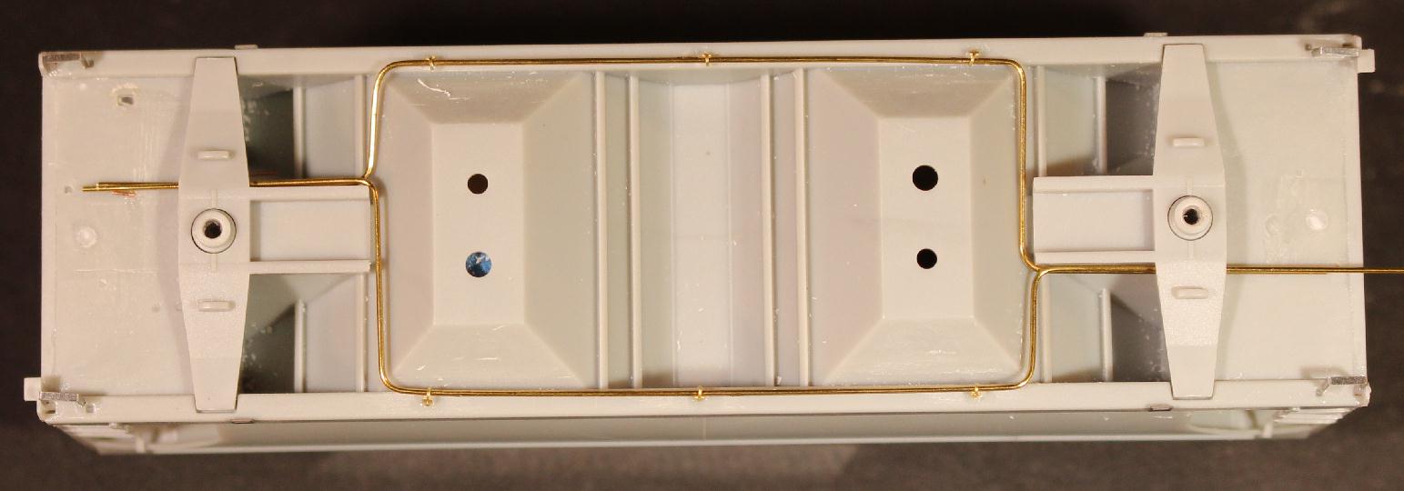
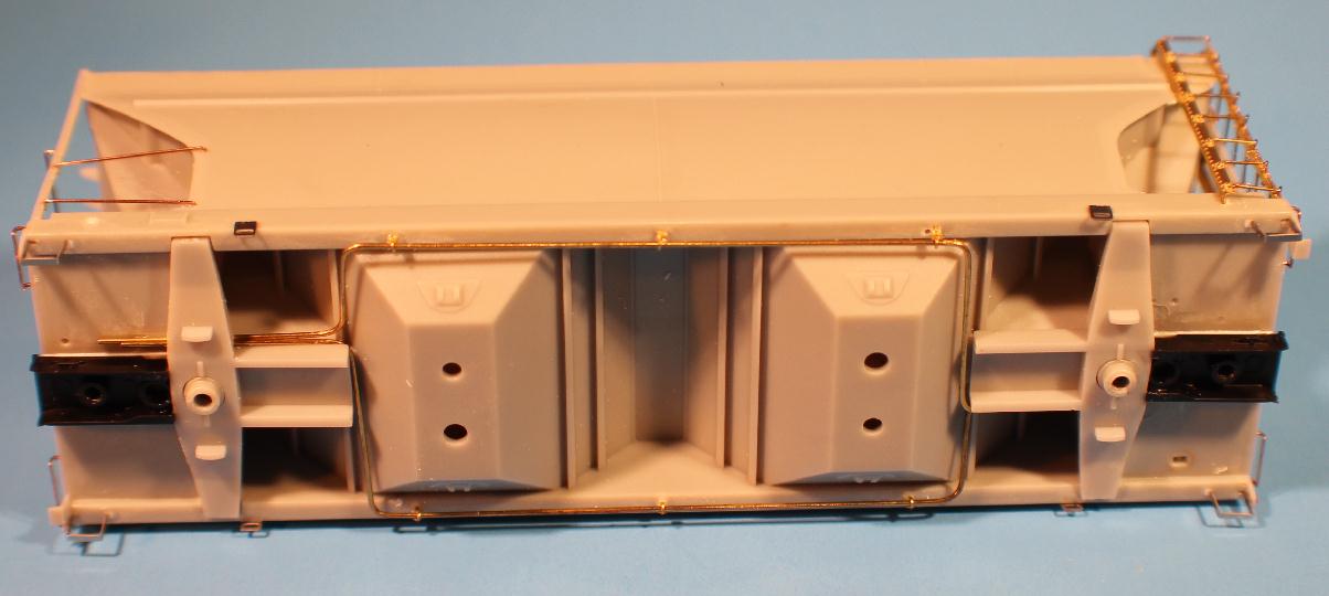
96620 Bottom view showing new train lines made of .020 brass wire. Replaced the stirrup steps with stainless ones. And replaced the rope pull tabs with stainless parts to get that flat plate look. |
|
96620 - Using the reference material I have, these cars can be considered a Phase I car. The length of these cars over the striker plates (coupler box face), should be 4.974" (or 36' 0.5"). This is about .121" (or 10.5") shorter than other cf2970 cars. To find out the length I need to trim the Moloco boxes to, I measured the distance to the outer ends of my modified bolsters. That length was 3.885". Cutting two boxes to .545 each, once mounted I was at the 4.974" needed. My .010" styrene shim was the length of the area between the car and the box, about .520", as I didn't want the shims exposed. |
|
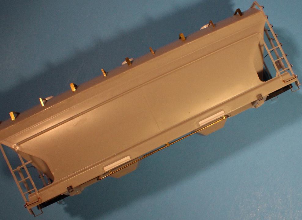
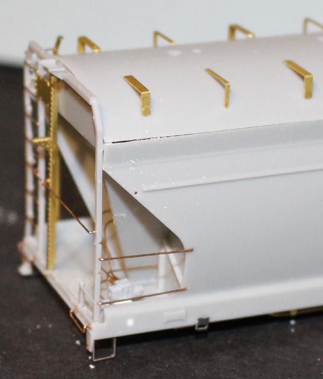
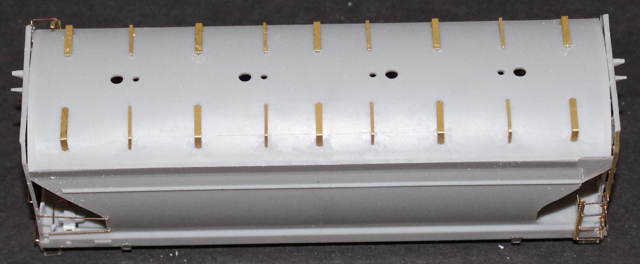
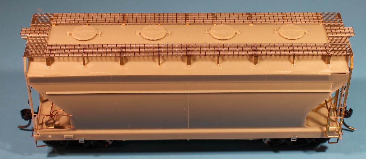
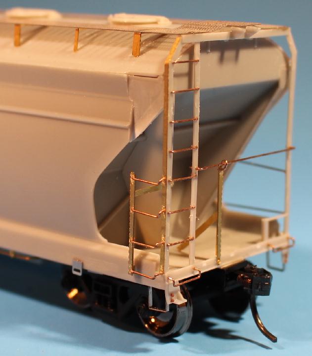
Top view showing the new brass roofwalk supports. Reused the top holes but drilled new lower holes. Wasn't completely satisfied with fit/look/shape if I had used the existing lower holes. |
|
New coupler crossover platforms were developed to use with these Athearn end cages. I tried three different mounting ideas, trying to get something that would represent the prototype but easily mount on the model. This is what I settled on. New Morton platforms will be added after painting. |
|
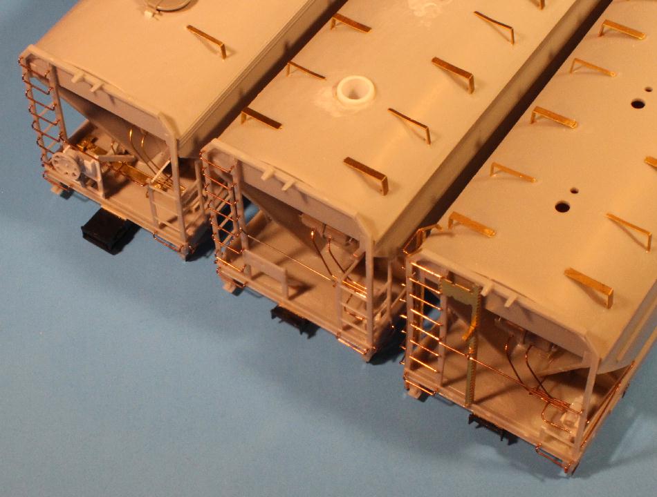
This photos shows some variety in the 2 bay ACF cars I am working on. The main thing about them and the reason I took the photo is the variation of the draft gear box positions. The lower right car is a 'phase I' CF2970 car. The box is barely visible. The middle car is a 'standard' CF2970. The top car is a CF2980 with a longer draft gear box. Not all cars are the same. |

|
I am procrastinating on the outlet gates so all of my ACF cars are in a holding pattern. This photos show the gate options I have. Going clockwise from upper left are: Intermountain 2980, Athearn 2970, Atlas 4650 and Accurail 4600. I will probably use the Athearn gates but I am trying to decide if I want to make any tweaks to them. |
|
96620 While I await that decision, I will post these photos of the car in a nearly done state. Here is a 'drone' view of the 96620 with the roofwalk attached. I used J-B Weld to attach it. Will be interesting to see how well it holds. |
|
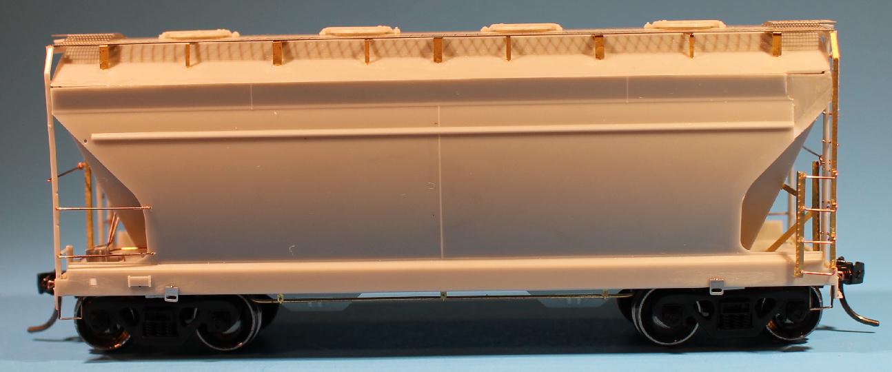
96620 A side view of the car as it is currently. Photos are always good to use as a tool to see where things need to be cleaned up and can be improved on. I have my list started... |
|
96620 A couple photos of the B end of the car. A new brake platform will be added soon. I need to make some tweaks to this end frame kit and figure a good way to get everything aligned easily. |
|
96620 A couple photos of the A end of the car. Used Kadee #158 couplers in the Moloco draft gear boxes. |
If you are interested in seeing the other models I am working on or planning to work on, >click here<
Have a comment, question, suggestion, info about this model project? Let me know - email

www.planomodelproducts.com