Modeling CNW 95787 PS2600 Covered hopper
CNW Series #95659-95869 - 210 cars
Built by Pullman Standard
At first glance, this series of cars look like a generic build of the PS2600 covered hopper and would be a straight forward build of the Athearn model. One of the variations that is easy to spot are the Pneumatic outlet tubes pointing toward each other on the inside surface of the bays. But something I didn't notice for a long time, was that the brake equipment on the B end is different than what I assumed all PS2600 covered hoppers have. I found this photo by Chris Butts that clearly shows a different configuration. So does that mean this series of cars have truck mounted brake cylinders? Not sure the technical info on these cars but I will attempt to model these variations and revise a few other details as I build this car.
| How to photos | How to description |
|---|---|

|
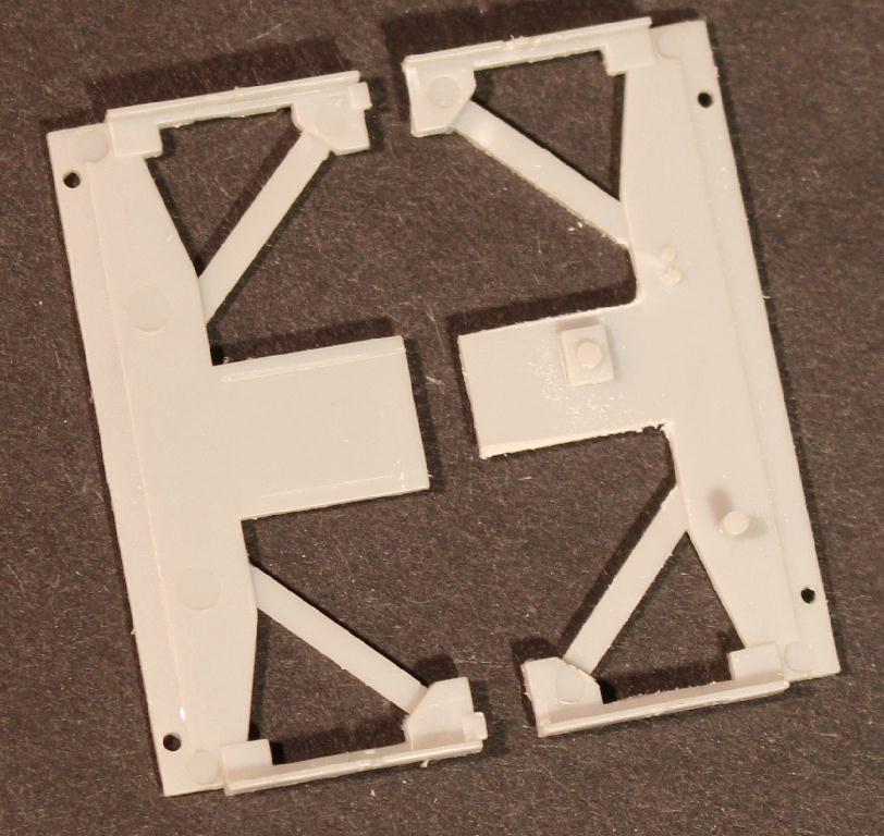
Starting with the main frame beam, I will be using Moloco replacement draft gear boxes on these cars, so I will need to remove the coupler boxes. I cut the existing box from the frame beam flush with the out edge of bolsters. The new box in this photo is just here for the photo. The new boxes will be cut to size and added toward the end of the build. |
|
Replacing the coupler boxes with Moloco draft gear boxes is going to be much easier task than I initially thought it would be.
There is actually a coupler box 'tongue' on the end frame that can be used to mount the new draft gear box to. It is about .060" wider than the new
draft gear so I am removing about .030" from each side. |
|
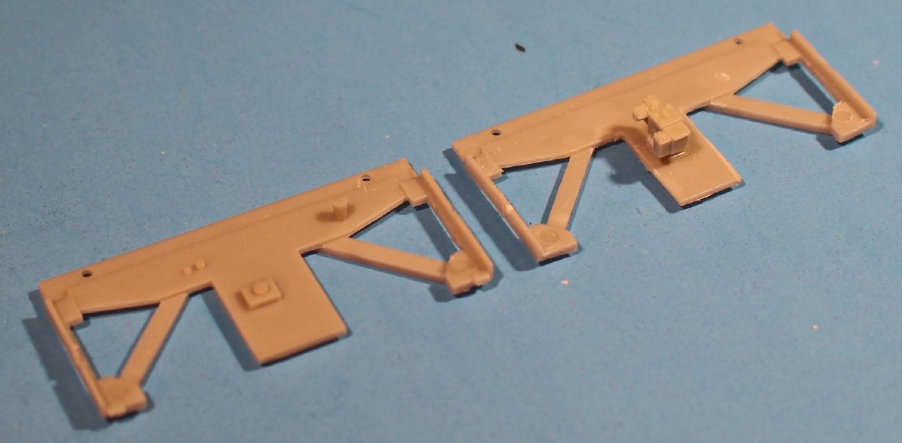
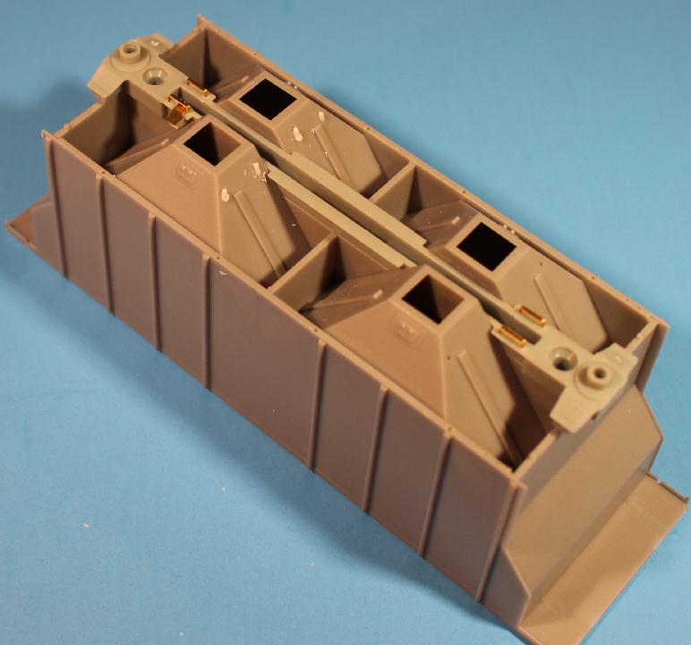
On the B end End Frame, there are mounting pins and pads for mounting the brake apparatus. I am only using the AB valve mounting pad, so I removed the air reservoir and brake cylinder mount pins. A new AB valve from the Tangent 4740 detail sprue was glued to the mounting pad after adding .030" shime to raise up. This will allow the air lines from the reservoir to be a little more even. A small .020" X .030" piece of styrene was used to plug the ladder slot in the side of the End Frame. And, there are alignment tabs on each end corner I removed, making the end flush across it. An original End Frame is also in picture for before and after reference. |
|
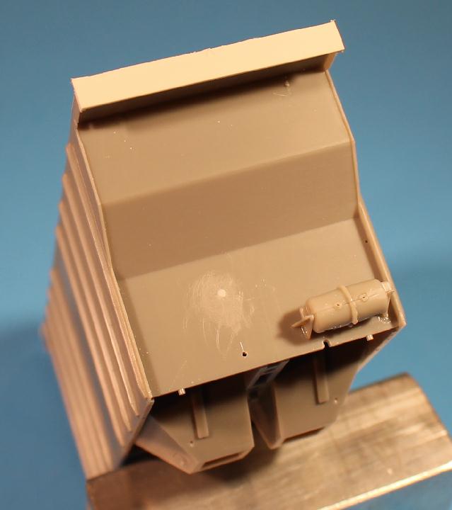
The Athearn Air Reservoir originally mounted on a pin on the End Frame. The prototype tanks are mounted on the end wall, so, I glued the air reservoir to the end wall after modifying the outer (right?) mounting bracket. The bracket was rectangular and I needed an angled one. Was able to use a razor saw to cut it an angle and remove part of mounting bracket. New air line holes are drilled in the reservoir to accept the new .012" wire lines I will be adding. |

|
The End Frames and Main Frame Beam are ready to be added. Getting the End Frame level turned out to be extra work now that I have removed the coupler box. If the original box was there I would have it to hold the end frame level. But not now. The end cage will have to work for now. Always something to plan ahead for. |

|
The end cage frames used on these models are slippery plastic. Not a fan of slippery plastic. I kind of understand why Athearn uses it. It seems stronger than regular plastic and looks to have crisper detail. But getting glue to stick and hold it in place? Athearn seems to have it figured out. I am concerned about my builds staying together and also the paint sticking. Yes I may build one using the slippery plastic to see how they do and look,
but for this build I am going to try something else. |
|
I toyed with the idea of making brass end cages much like I did for the PS2 4427 covered hopper. Just wasn't sure it was worth the
extra effort and expense of development for the result I was going to end up with. Lots of extra angles and bends in these posts. |

|
While bouncing from project to project, planning what I need to get and do for the other cars I am building (you think I work on one thing at a time? hahaha),
I was looking over my Tangent PS 4000 covered hopper kits. Something about those end frames looked very familiar. Doing some comparisons
lead me to believe I could make these work on this PS2600 project. |
|
The bottom cross frame will mate up to the End Frame, but it is narrower by .100" And new top plates needed to be made out of .020" thick styrene. While examining all of these new end cage addition needs, I found that the upper corners of the body needed to be built up/out. Slightly cleaning the corners and adding small pieces of .030" X .030" styrene squared up the corners. This filled in the cornes for the new end plates and also gave a better side surface for new corner posts. |
|
|
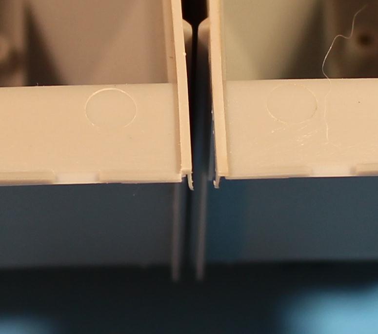
You might have been wondering what that white strip was in one of the photos above. That is the new end top plate I need to add. Pieces of .020" styrene were used for the new upper ends panels. I used some approximately .150" X 1.400 pieces and glued them centered on the upper end. The bottom is flush with the added corner styrene, which are flush with the bottom of the corner triangle on the body. Any extra material on the sides is filed even with the sides. |
|
|
With these two new end panels glued in place (and dry) the roof will still fit in place between them. To trim the end panels to match the angle of the roof, first I added tape to the roof to protect it and then carved and filed the panels down. After the roof is glued in place, I will do some final sanding to clean the joining surfaces up. |
|
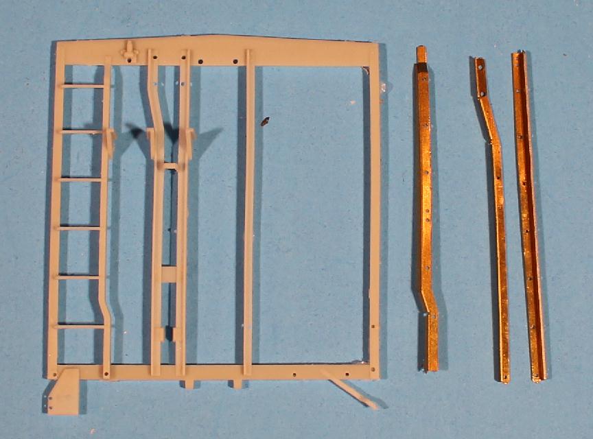
With the coupler boxes removed, I can now add some details to the frame beam. I removed the plastic brake levers from the main frame beam and replaced them with brass levers. This includes new linkage and hanger brackets. The etched levers and hangers are some I had etched. |
|
|
Next? |
Have a comment, question, suggestion, info about this model project? Let me know - email

www.planomodelproducts.com