Disclaimer - While my intension was to have a well-organized page of my cf 2980 detailing projects, this page isn't there yet. I admit I was trying to do too many models at one time and got ahead of myself at times. I do plan to go back and redo this page, but after the 2015 St.Louis RPM meet unvailing, I wanted to have something out there so others could see what I have done so far and how. Your patience and understanding is appreciated. I am just trying to have fun and share my modeling adventures with others.
For now I will be building two of these models using InterMountain
undecorated kits #41599 . The basic shell of this model will work fine and satisfies my needs to represent this series of covered hoppers. But I will be replacing several small details on these cars. For some people, the detail may be fine and the model is something to fill a train. But I want to bring this car up to what I consider 2015 standards. So follow along if you want. I am really excited to finally be building these cars.
| How to photos | How to description |
|---|---|
|
Started by removing some of the cast on details on the main
body. Not too many to remove. The grab irons and stirrup steps
on the corners. The cut lever and stirrup brackets on the ends.
And the hardest to remove, the shaker pockets on the sides of
the bays. Not really hard but tedious. I used NWSL sanding sticks and slowly sanded them away. |
|
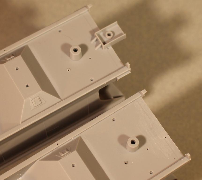
I will also be replacing the coupler pockets with Moloco Draft Gear boxes. So I used a mill to remove the plastic boxes flush with the bottom of the deck. There will be more involved with adding the new pockets and I will get in to that later. Getting the right coupler height will be a new challenge for me. Getting them placed right will also be critical as they will give the correct car length over the strikers. The bolsters also needed to be trimmed back. Will want the extra mounting surface. Plus there is a width difference between them and the new draft gear. |
|
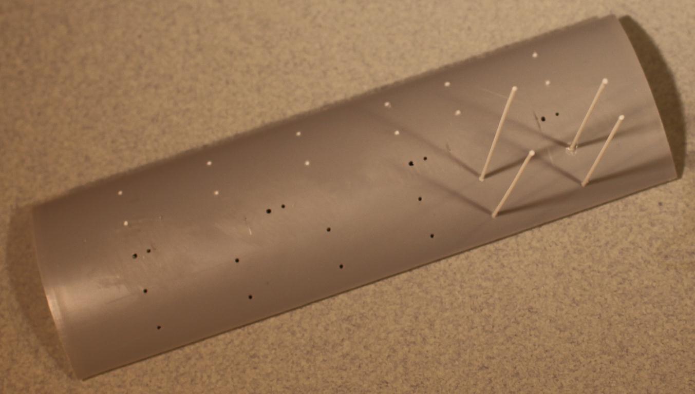
The roof needed to be cleaned up. Yes, this model is supplied with independent plastic walkway supports and this is a step in the right direction from a model manufacturer. But I will be using the brass supports that come with the walkways. All of the support mounting holes are filled with .035 styrene rod. The spacing for the four 30" hatches is different on this car than that of the model so the small round hatch mounting pads are sanded off and hatch mounting holes filled. |
|
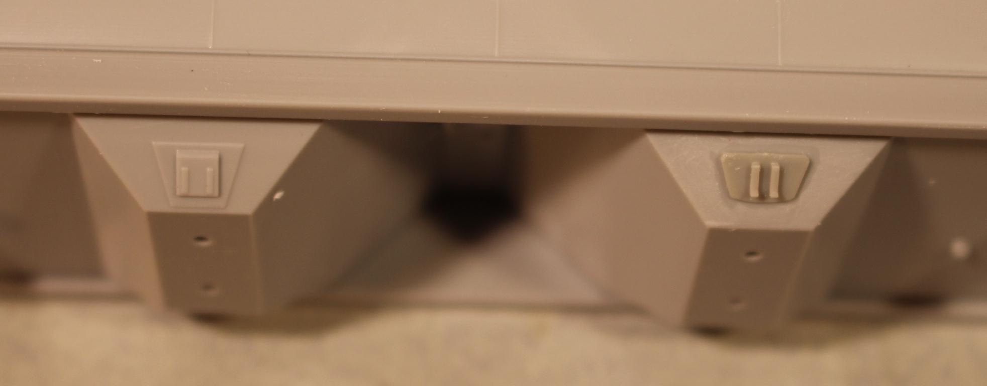
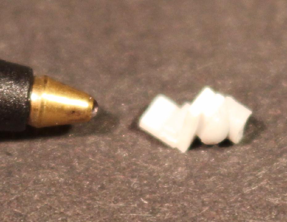
Time to add some of the new details. Those shaker pockets I removed are being replaced with parts from Atlas. Atlas uses some nice representation parts on their 4650 cf model. Atlas sells these parts #140020 in their parts store which is great for those like me who like replacing parts. A slight modification was needed before I could add them to the model. On the back side of these castings are 'Keying' protrusions that help assemblers get them in the right spot on the 4650 model. Well, I don't have those keying slots on this model. So I filed the protrusions off. *note* I discovered it is better to leave them on the sprue while sanding the back smooth. Holding one independently flat on the finger works but should it not stay on the finger, it will fall into the great abyss - the floor. How can something disappear on the floor? Oh wait - my work space/office is a 'enter at my own risk! Never mind... |
|
Placement of the new shaker pockets is visual for me. I can assume ACF builders had a dimension at which they welded these in place but I do not know what that dimension is. David Olsen has a great dead on shot of one posted on his rrpicturearchives web page. So from a side view I see it just below the brake line. Works for me. A comparison of old and new. |
|
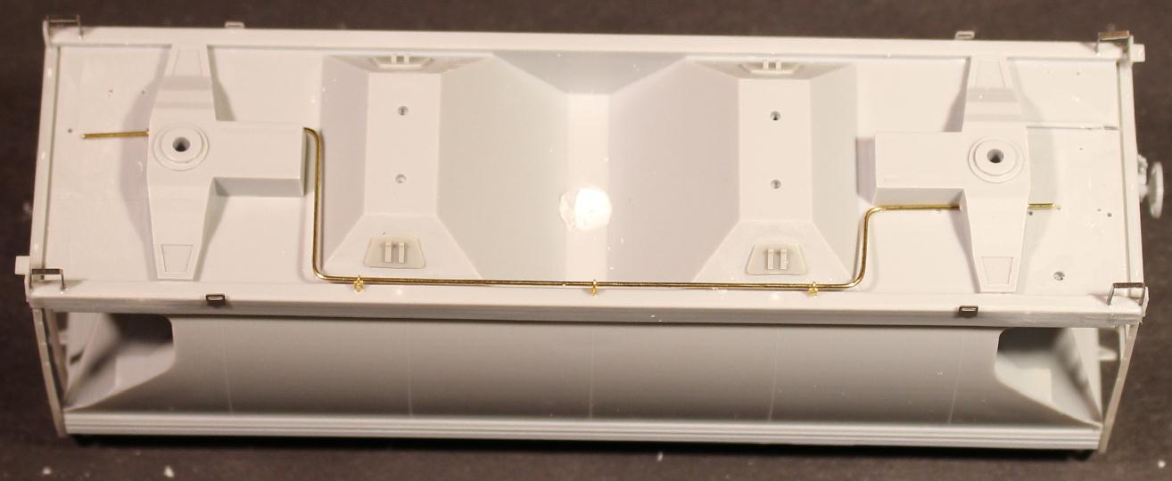
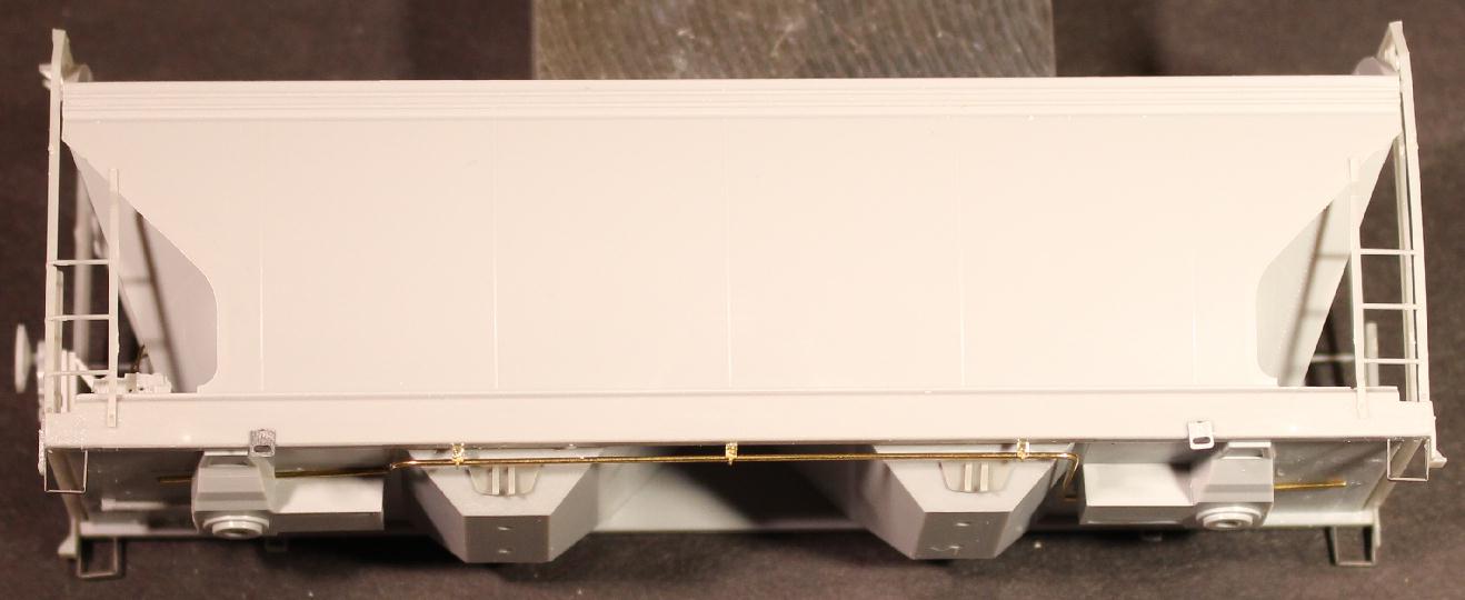
Using .020" brass wire, I bent new train lines. For the most part I followed the provided plastic lines that come with the model. I went ahead and made them full length. Won't really see all that but I did it anyway. To hang the lines I used my #10886 train line hangers on the sides. The ends feed through holes drilled in the bolster parts. Something I had to keep in mind while bending these was to keep them close to the side of the new coupler pockets that aren't there yet. |
|
On the end walls of some ACF 2980s there are small angled stiffener braces. InterMountain did not add these to their model and that is understandable as not all prototypes had them. Easier to add than remove. CNW had them and these braces are real easy to add. If you look at photos, the outer end is approximately up .150" from the end deck and the inner end is about .375 from the end deck, or about even with the top of the large center access hole. I used pieces of .015 X .030 X .375 styrene and MEK'd them in place. |
Brake equipment. Here is an area I spent a bunch of time studying and pondering. One of the considerations was what I will call consistency. Remember, this model was first produced in 1999(?), the year I bought these kits. The brake equipment is OK but I wanted to compare it with fine detail of today's top of the line models, thanks to Tangent, ExactRail and others. And I am going to try to be consistent now that I am finally building some models. That consistency means using some of the higher quality details available today. So I started going through my stash of covered hopper kits to compare the different brake equipment parts to see if there were any I preferred to use. After reviewing the various kits and seeing which parts were available from the various manufacturers, I order the following sets, just to make sure I had various parts available, not for just this build but for the others I am working on as well. Tangent 4750 brake details, the Tangent #95000-06 4740 brake details and the Atlas #8820000008 HO 5701 Ctrflo hopper brake details |
|
|
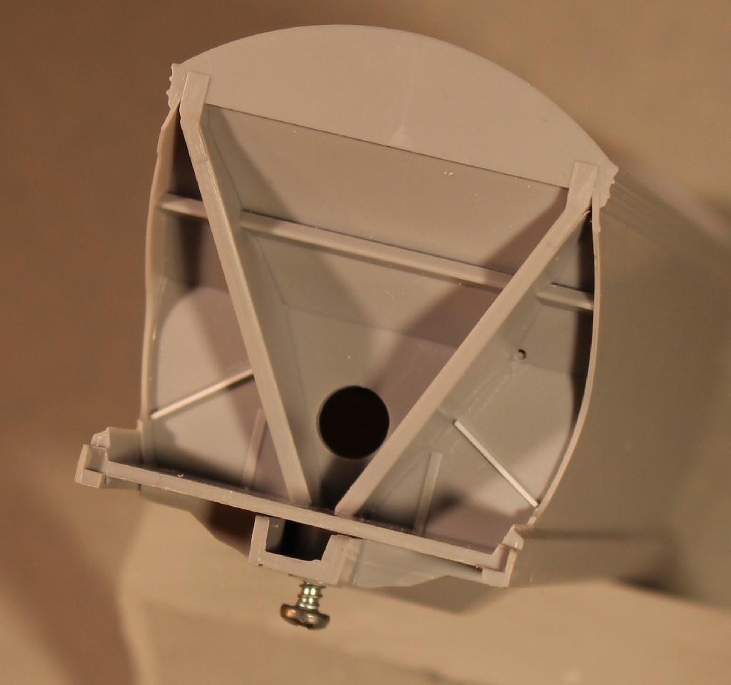
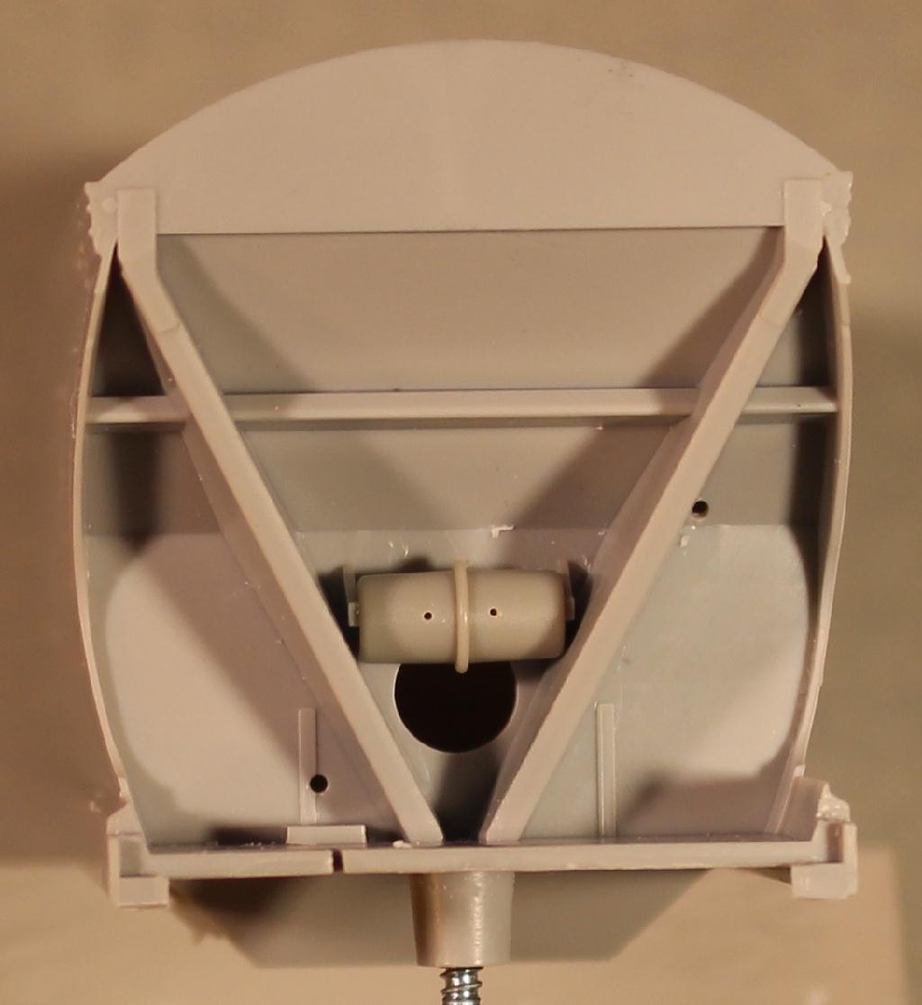
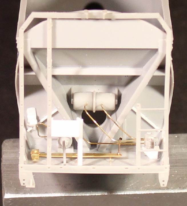
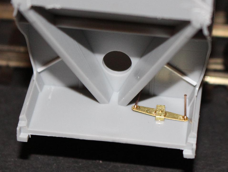
On the brake reservoir, I also had to consider the width of it. Because of the taper required to cast the Slope Sheet Supports on the ends, the width of the opening is slightly reduced. Something that does help in the width is, from what I can see, ACF mounted there air tanks up to the triangular gussets vs. the down on like Pullman Standard (PS). I had a couple options, make gussets and use one of the air tanks without gussets or use an air tank with gussets cast on. The one that will fit my requirement is actually the one from the bag of parts that came with the shaker pockets from Atlas. |
Knowing that I will be mounting these air tanks on more than one model, I made a styrene template to fit inside the V shape where the tank will mount. This template will save me from measuring and marking where to drill over and over. Just place it on the B end, mark the hole location and drill a .040" hole to mount the tank. The old holes could have been filled but I won't see them once the new tank is mounted. |
|
|
For the AB brake valve, after all that pondering, I will be using the Intermountain one supplied with the kit. Before mounting I drilled four .012" for brake lines. The valve is mounted in the same location as the IRC valve. Their mounting provision is a round peg in a round hole with a round post holding it up. I removed that pin and made a U channel support to sit it on. Probably could/should make an etching for this purpose. Got-to-stop-etching-everything... |
|
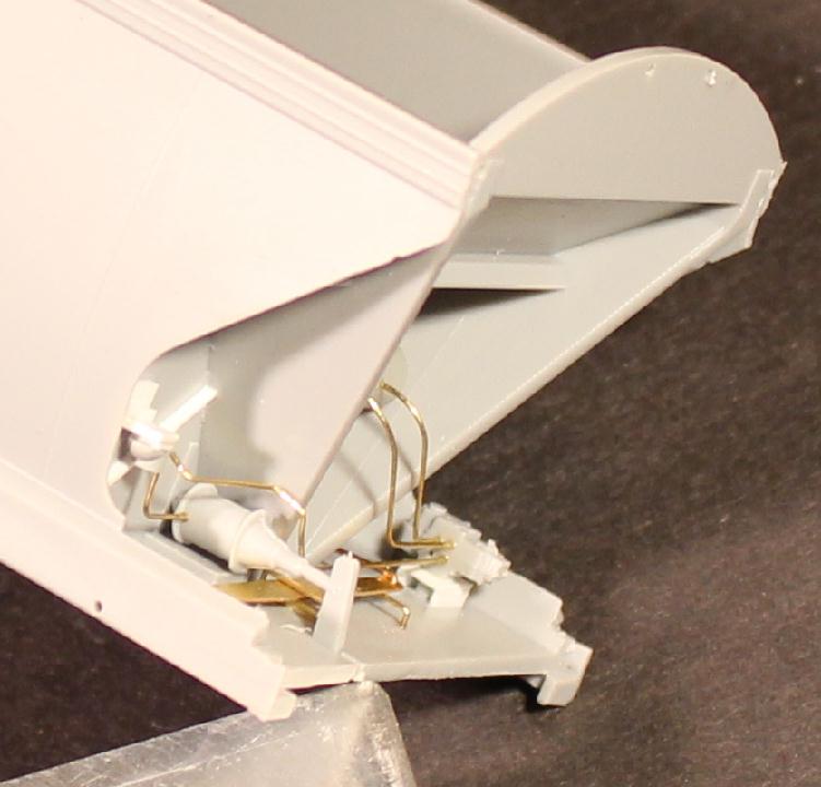
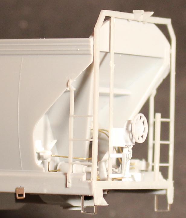
Above you will recall I spent a lot of time studying and pondering. Well that is because I do not have any defining shots that show what the rigging looks like on these CNW cars. I have a basic idea but a few of the details are questionable. After a lot of searching and comparing and pondering, here is what I came up with. The brake cylinder/lever/fulcrum are ones supplied with this model. The long brake lever is a brass etching. Could have made this out of styrene but well it's me... A .030" hole is drilled in the end wall straight back from the hole in the brake lever and a .015 brass wire feed from the lever through the hole. |
|
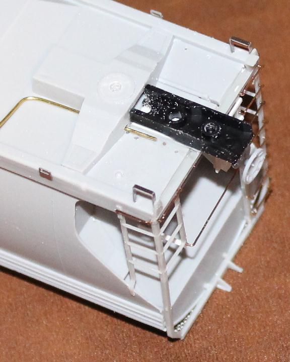
There is some kind of valve or something mounted on the wall up
diagonally from the brake cylinder. I don't know what it is (yet)
and I have not found one being produced as a detail part. So I
improvised. Again I thank Mr. Olsen for all of his detail shots he
posts on his photo site. As you can see from this photo there isn't a lot to this detail. So I took some scraps of styrene and a small piece of a detail sprue and came up with my version. Good
enough for me. Almost forgot to drill two holes for the air lines
before I mounted it. |
|
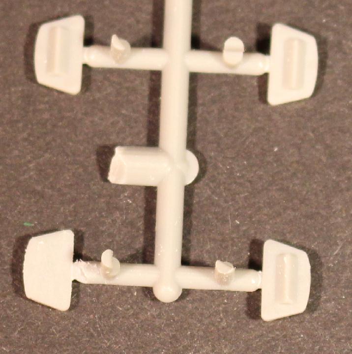
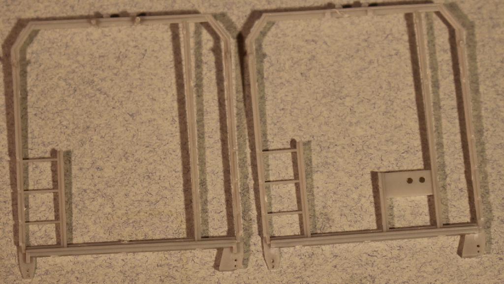
I am replacing the InterMountain end cages with the 2970 cages available from Athearn P/N 93990. Surprisingly these are a very good fit and take minimal work for the initial fit. In the lower corners there are some alignment tabs that need to be removed. And that is it. The cage on the left is an unmodified A end cage. One on the right is B end frame, modified to fit. Notice the tabs in the lower corners are the only difference. On this first build I am using their upper mounting pins. Not sure I would have to. Could probably clip the mounting pins off and glue the ends right to the body. |
|
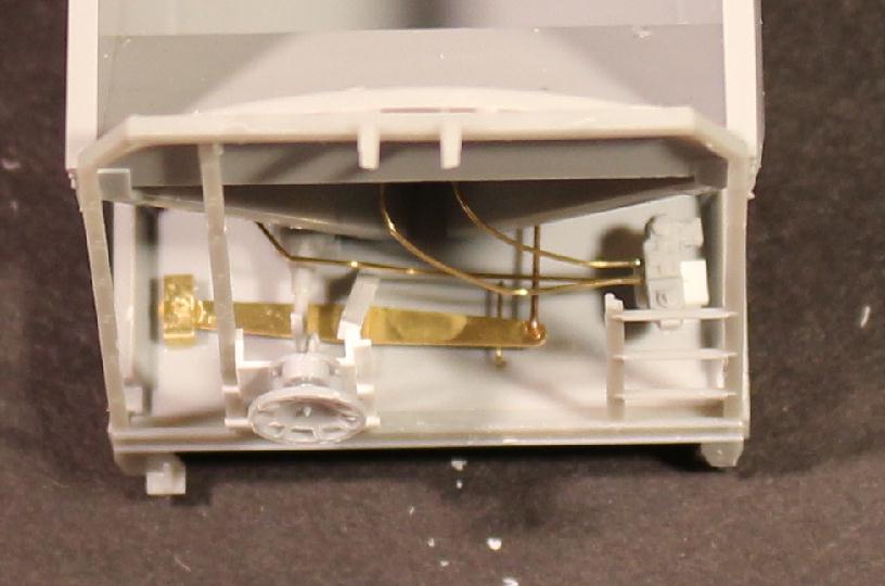
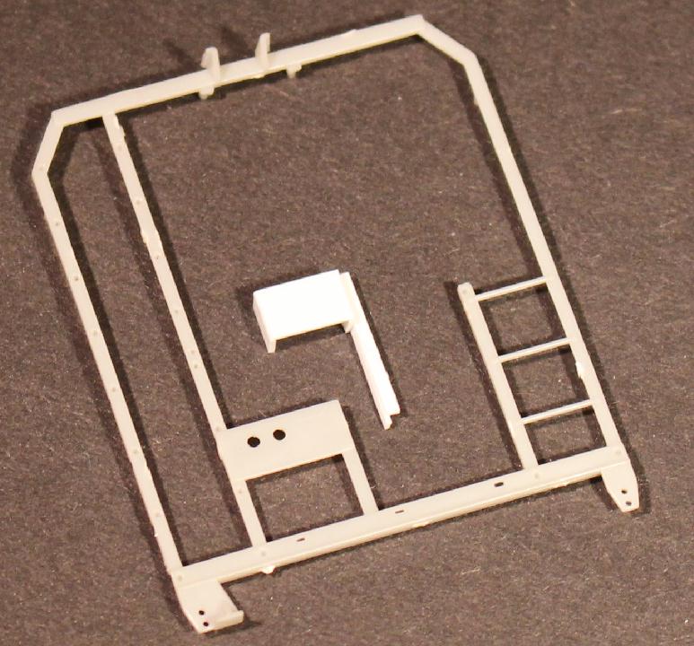
Unfortunately the brake housing mounting is different than the Athearn 2970. Here I used the InterMountain end as a reference and build a new mounting plate from styrene. A piece of .010 X .030 X .450 styrene glued to the side of a .010 X .040 X .420 styrene gives me a new angle iron upright. A piece of .015 X .156 styrene strip mounted to two .015 X.080 X .156 styrene strips was glued between the ladder and the upright giving me a plate to mount the brake housing on. There is also a bracket from about the top of the angle iron post angled down to the deck. A couple small strips on each side of the fulcrum for support. |
|
The side ladders are also Athearn parts, P/N 93991. There is a small tab on the bottom that is removed. The rungs glue to the corner post. The top should glue behind the side wall to represent a Phase II car, but it just wouldn't fit and look right. So I glued it to the outside. And the bottom glued where it landed. New lower grab irons are added along with new stainless steel stirrup steps. You can also see that I used a brake housing and wheel from Tangent 4750 brake set. |
|
The A end is a lot easier. The etched brake lever was mounted to the floor and two .015� wires attached and fed through .030 holes drilled in the end wall. |
The A end cages were now added. Remove the lower corner tabs, glue the end cage in place, add small styrene support between the short ladder and the end slope support, Side ladders, lower grabs and stirrups. |
|
|
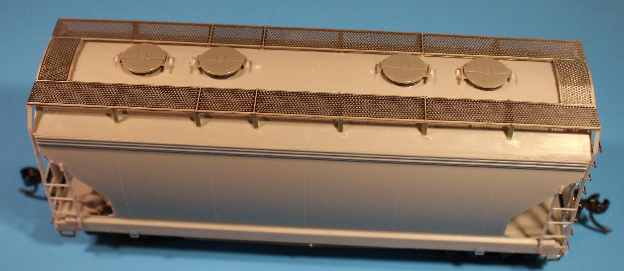
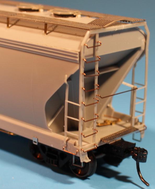
Here is a side view showing several of the new details added. The sides are pretty much done at this paoint. |
I made all new grab irons out of .012" phos. bronze wire. Took a few attempts to get the hang of it. I am fine with the results. I have some of the metal grabs that Athearn supplies with the 2970 kits. Don't know what I was doing wrong but I could not get them to glue in place. The CA just wouldn't set up. These set instantly. Is there something about the CA and that metal react against each other? It was less work to make new ones then fight the metal ones.
|
|
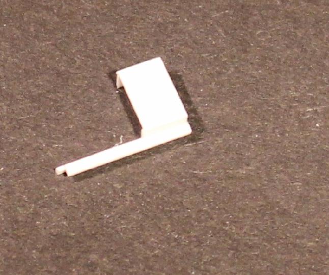
New coupler crossover platforms were developed to use with these Athearn end cages. I tried three different mounting ideas trying to get something that would represent the prototype but easily mount on the model. This is what I settled on. New Morton platforms will be added after painting. |
|
|
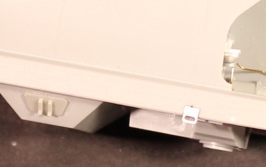
The rope pulls that come with the car are fine but I decided to replace them with stainless steel plates. Filled the mounting holes with .025 styrene rod. The rope pulls on these cars look like they are set further in. So I relocated them just below the outer weld lines on the car side. New .012" holes were drilled and new stainless new plates CA'd in place. |
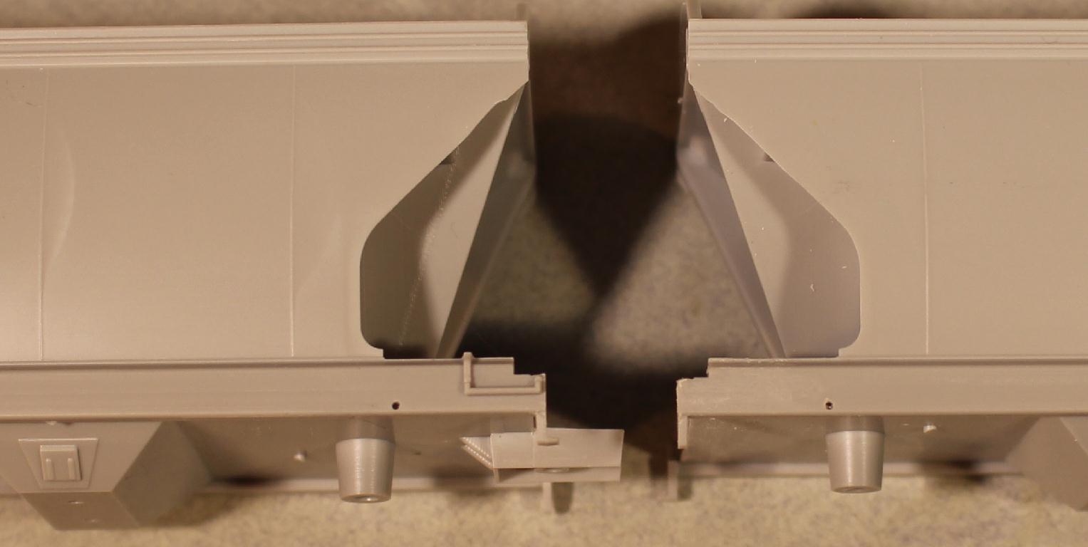
It is time to add the Moloco draft gear boxes. Getting the new boxes centered isn't what concerns me, it is getting them the correct height. I assembled a box with a #158 Kadee and taped it to the bottom of the deck. I will be using AccuRail 125 ton truck frames and InterMountain 36" metal wheels on these cars. I mounted them on the car and set car on a track to check the height. I found there was a slight difference as I expected. A piece of .020" styrene between the deck bottom and coupler box to achieve an acceptable coupler height will be needed. |
|
|
Using the reference material I have, the length of the car over the striker plates (coupler box face) should be around 5.416" (or 39' 3"). To find out the length I need to trim the Moloco boxes to, I measured the distance to the outer ends of the modified bolsters. That length was 3.920". Cutting two boxes to .748 each, once mounted, I was at the 5.416" needed. My .020" styrene shim was the length of the area between the car and the box, about .520", as I didn't want the shim exposed |
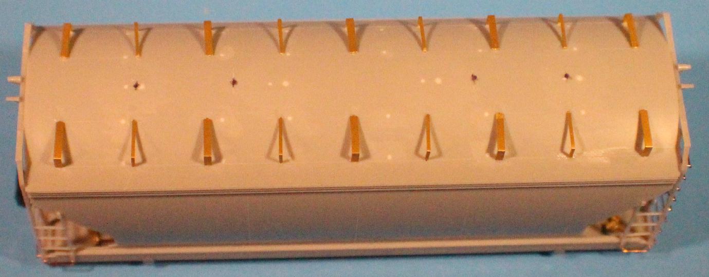
Before I attached the roof to the body I drilled the holes for the brass walkway supports, using one of those fancy paper templates. Yes I use them too. |
|
|
As I alluded to earlier, the spacing of the roof hatches on this series of CNW cars is different than the spacing of the roof hatches on the model. The spacing I need is four 30" hatches centered on the roof with the spacing of .707" (5' 1.5") - 1.771"(12' 10") - .707"(5' 1.5"). Going from the center of the roof I measured out .886 and .707 for my new hatch locations. |
|
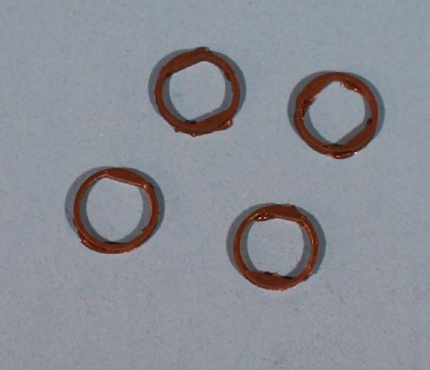
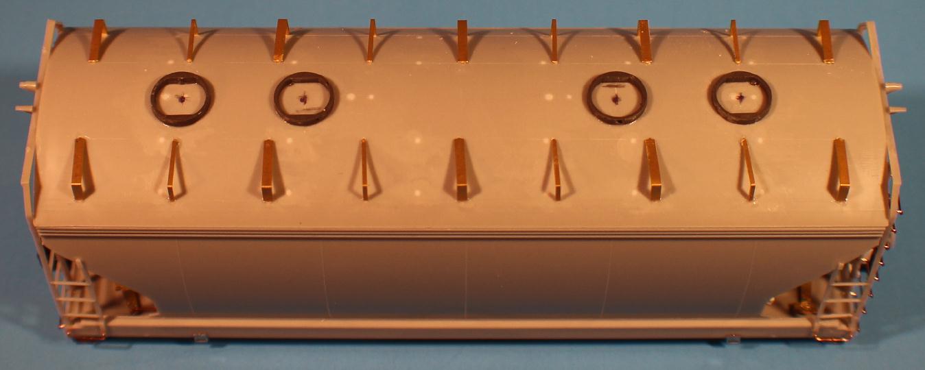
update For the hatches, I am using Tangent's 30" hatches from their 4000cf PS2 covered hopper. But how to mount them. I considered making new "rims" from .030 X .030 styrene strip. But that didn't work out too well. Next I tried casting some rings. Turned out OK but still a lot of extra work. I could carefully carve the rings off of the Tangent 4000 roof. Could... I have now found some Evergreen tubing that is very close to the size that will work for me. Too late to use on this car but will use on future builds, including the PS3148 CNW rebuilds. |
|
Had to file a slight bevel in the rings to match the contour of the roof. Centered the rings over the new hatch locations and glued in place. Placement just don't look normal, does it? After the Tangent hatches are attached, I inserted a small .030 x .030 piece of styrene between the hatch hinge and latch and the roof so they wouldn't look like they are suspended in air. The more I look at photos, I don't believe these blocks are needed. I think the hinge strap bends back against the manway shute. More research needed.... |
|
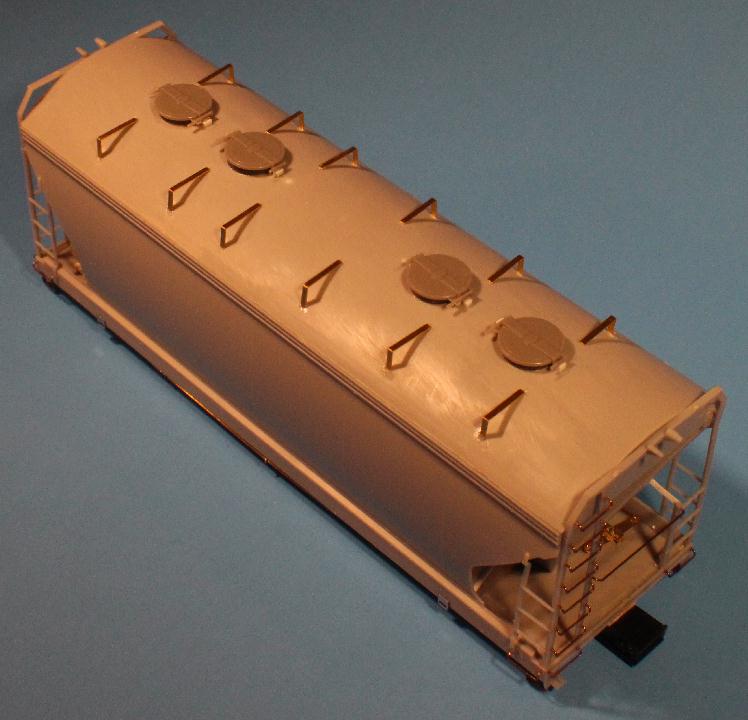
While I procrastinate on what to use for the outlet gates, here are some photos of the cars as they are right now. This 'drone' view shows the Morton pattern roofwalk applied. |
|
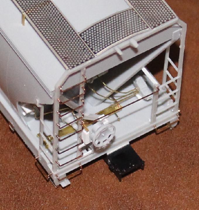
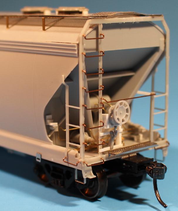
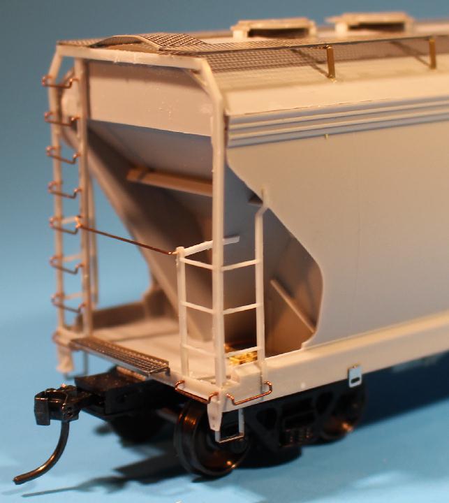
Here are a couple different angles of the B end of the car. I used Kadee #158 couplers. The trucks are Accurails with InterMountain 36" metal wheels. The coupler crossover platforms have been added here, but future builds will have them added after painting. I haven't seen any Morton crossover platforms that are painted. |
|
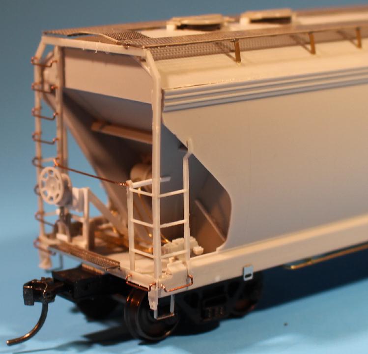
A couple views of the A end of the car. There are a few little areas on this model that need to be finished up before painting. But most of the car is done. |
|
next |
If you are interested in seeing the other models I am working on or planning to work on, >click here<
Have a comment, question, suggestion, info about this model project? Let me know - email

www.planomodelproducts.com